Heat Balance Calculation for Reactors and Jacketed Vessels: A Practical Engineering Guide
Most heat balance disputes don’t happen because someone forgot the energy balance equation. They happen because two engineers used different correction factors for the jacket LMTD, or because someone forgot to add the start-up heating margin before sizing the cooling water line — and the design package gets sent for review with a duty that’s 15% off from what the plant actually needs.
We see this constantly when reviewing third-party packages for EPC clients: the math isn’t wrong, exactly. It’s incomplete. This guide walks through a real reactor heat balance from reaction duty all the way to closure check, the way we’d actually do it on a live project — not the simplified version you’d find in a process fundamentals textbook.
What a Heat Balance Actually Needs to Account For
A reactor heat balance isn’t just “heat generated equals heat removed.” On paper, sure. In practice, you’re tracking several heat flows at once:
Heat of reaction (the exothermic or endothermic duty from the chemistry itself)
Heat losses to ambient through the vessel wall and insulation
Jacket-side heat transfer, including the correction factor for whatever flow pattern your jacket actually uses
Any heat recovered through process integration (pinch analysis) before it hits the utility system
Skip any one of these and your “closed” balance is closed on paper only. The plant won’t know the difference between a 4% closure error and a 15% one until the cooling water system can’t keep up during a hot batch.
Step 1 — Establish the Reaction Duty
Say you’re running an exothermic batch reaction releasing 765.6 kW at steady-state conversion. This number usually comes from the reaction kinetics package or lab calorimetry data — it’s an input to the heat balance, not something you calculate from scratch inside the spreadsheet.
This is the baseline. Everything downstream gets sized against it, but rarely equal to it — and that’s where a lot of first-pass calculations go wrong.
Step 2 — Size the Jacket Duty (Not the Same as Reaction Duty)
Here’s the part people skip: the jacket has to handle more than just the reaction heat. It also needs margin for:
Start-up sensible heating of the batch before reaction kicks in
A control margin so the cooling system isn’t running at 100% capacity during normal operation (no headroom for upsets)
Ambient losses, which are usually small but not zero on a large vessel
On this reactor, accounting for those, the jacket design duty comes out to 880.4 kW — about 15% above the steady-state reaction duty. That 15% isn’t arbitrary; it’s a fairly standard design margin for batch reactors with moderate ambient exposure, though we’ll adjust it up for reactors running in uninsulated outdoor installations.
Margin = (880.4 − 765.6) / 765.6 = 15.0%
If your jacket duty comes back equal to your reaction duty, that’s usually a sign the margin got left out, not a sign of an efficient design.
Step 3 — Calculate Required Cooling Water Flow
Now you size the utility side. The governing equation is the one every engineer knows:
Q = ṁ × Cp × ΔT
Rearranged for flow:
ṁ = Q / (Cp × ΔT)
Take cooling water entering the jacket at 28°C and leaving at 41°C — a ΔT of 13°C, which is on the higher end but reasonable if your cooling tower can support it and you’re trying to minimize pumping cost.
That’s your required cooling water flow. Notice how sensitive this number is to ΔT — drop the temperature rise to 8°C instead of 13°C, and your required flow jumps to over 95 m³/hr for the same duty. This is exactly the kind of trade-off worth running a few scenarios on before you lock the utility line size, because re-sizing a cooling water header after piping isometrics are issued is a conversation nobody wants to have.
Step 4 — Apply the LMTD Correction Factor
Straight LMTD assumes ideal counter-current flow. Most jacketed vessels don’t give you that — annular jackets and half-pipe coils have flow patterns that fall short of true counter-current, so you apply a correction factor F to the ideal LMTD.
For this reactor, the ideal LMTD works out to 22.8°C, and with a correction factor of F = 0.94 (typical for a half-pipe coil jacket at this flow configuration):
LMTD_corrected = 22.8°C × 0.94 = 21.5°C
Skip this correction and you’ll undersize your heat transfer area by a meaningful margin — small on paper, but it compounds when you’re also using slightly optimistic fouling factors elsewhere in the calc.
Step 5 — Back-Calculate Required Heat Transfer Area
With duty and corrected LMTD known, solve for area using an assumed overall heat transfer coefficient. For a glass-lined or stainless jacketed vessel with water on the jacket side and a moderately viscous process fluid inside, U typically falls between 250–400 W/m²·K depending on agitation and fouling allowance. Using U = 400 W/m²·K:
A = Q / (U × LMTD) = 880,400 / (400 × 21.5) = 102.4 m²
If that area doesn’t match what your vessel’s jacket can physically provide, you’re not done — you either need a higher U (better agitation, less fouling margin) or a larger vessel jacket surface, and that conversation needs to happen before procurement, not after the vessel is fabricated.
Step 6 — Heat Integration and Pinch Recovery
Before any of this duty hits the utility system, check whether process-to-process heat recovery is on the table. In this case, pinch analysis across the unit identified 421 kW of recoverable heat — likely by preheating a cold feed stream against a hot product stream that would otherwise just go to a cooler.
That’s nearly half the reactor’s reaction duty recovered before it ever touches a utility. On a plant running multiple batches a day, that’s a real number on the utility bill, not a rounding exercise.
Step 7 — Close the Balance
Sum every heat input and every heat output across the system — reaction duty, sensible heating, losses, recovered heat, utility duty — and check the gap between them.
Closure error = |Heat in − Heat out| / Total heat in
A closure error under 5% is generally treated as a pass for process design purposes; anything wider and you go back through the balance line by line until you find where the gap is coming from. On this reactor, the balance closes at 4.6% — tight enough to issue for design, with the gap most likely sitting in unaccounted ambient losses or measurement tolerance on the reaction calorimetry data.
Where This Goes Wrong on Real Projects
A few patterns show up again and again when we audit third-party heat balances:
No margin between reaction duty and jacket duty. If they’re identical, someone forgot start-up heating or control margin — and the cooling system will be marginal from day one.
Uncorrected LMTD. Treating the jacket as a true counter-current exchanger when it’s a half-pipe coil or single-pass annular jacket. The math looks clean; the area comes out undersized.
Pinch opportunities never checked. Engineers size the utility duty straight off the raw reaction heat without asking whether any of it could be recovered internally first. It’s not wrong, it’s just leaving money on the table.
Closure errors buried instead of investigated. A 12% closure gap doesn’t mean “close enough” — it means something is missing from the balance, and it’s usually a stream someone forgot to map.
Getting This Right, Consistently
The fix isn’t more careful manual math — it’s a calculation structure that won’t let you skip a step. That’s the entire premise behind our Heat Balance Workbook: 12 sheets, 2,609 cells, built so the jacket margin, LMTD correction, pinch check, and closure validation all happen in sequence and auto-update if you change an upstream input.
[Download the Heat Balance Workbook → Get Instant Access (₹3,999)]
If your plant has a more unusual configuration — multiple reactors sharing a utility loop, or a continuous process instead of batch — the templated sheet gets you most of the way, but not all the way.
[Request a Custom Heat Balance Calculation from Our Engineering Team][Schedule a Free Engineering Consultation]
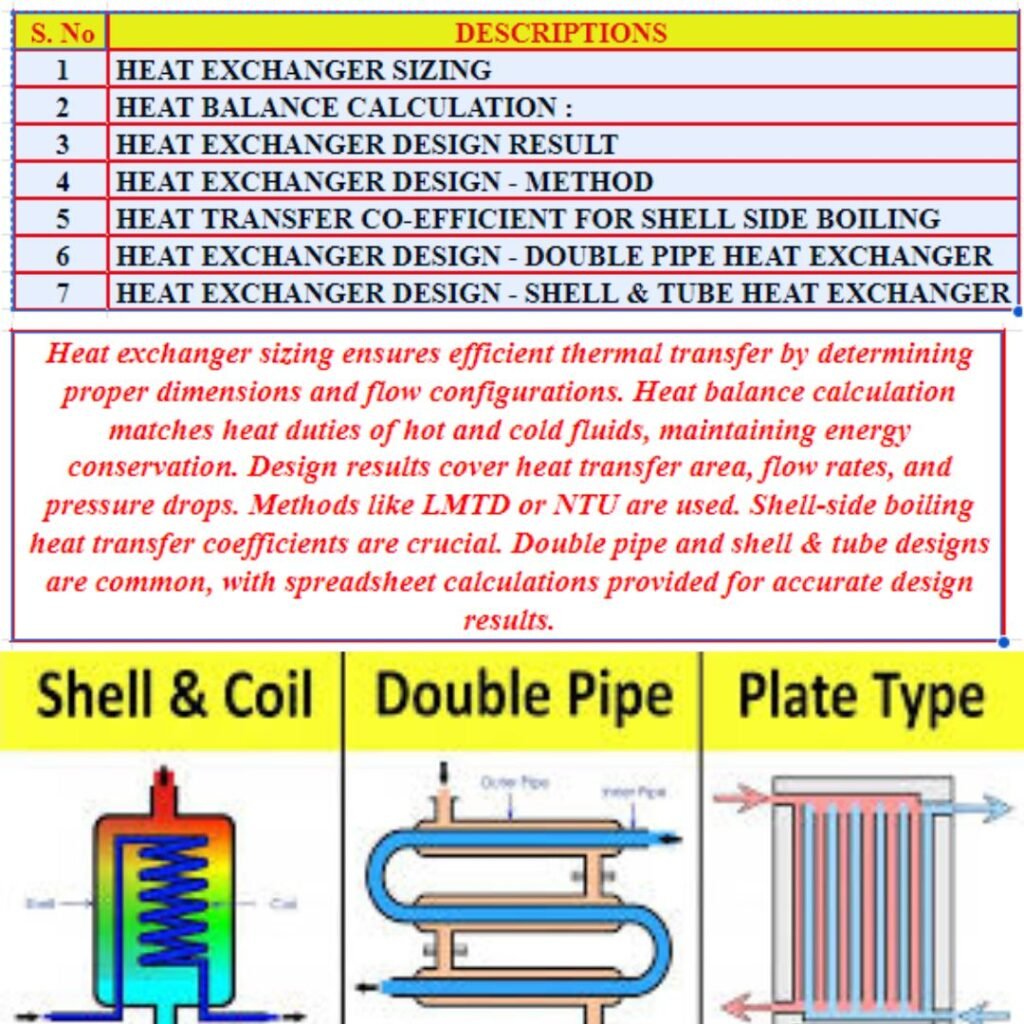
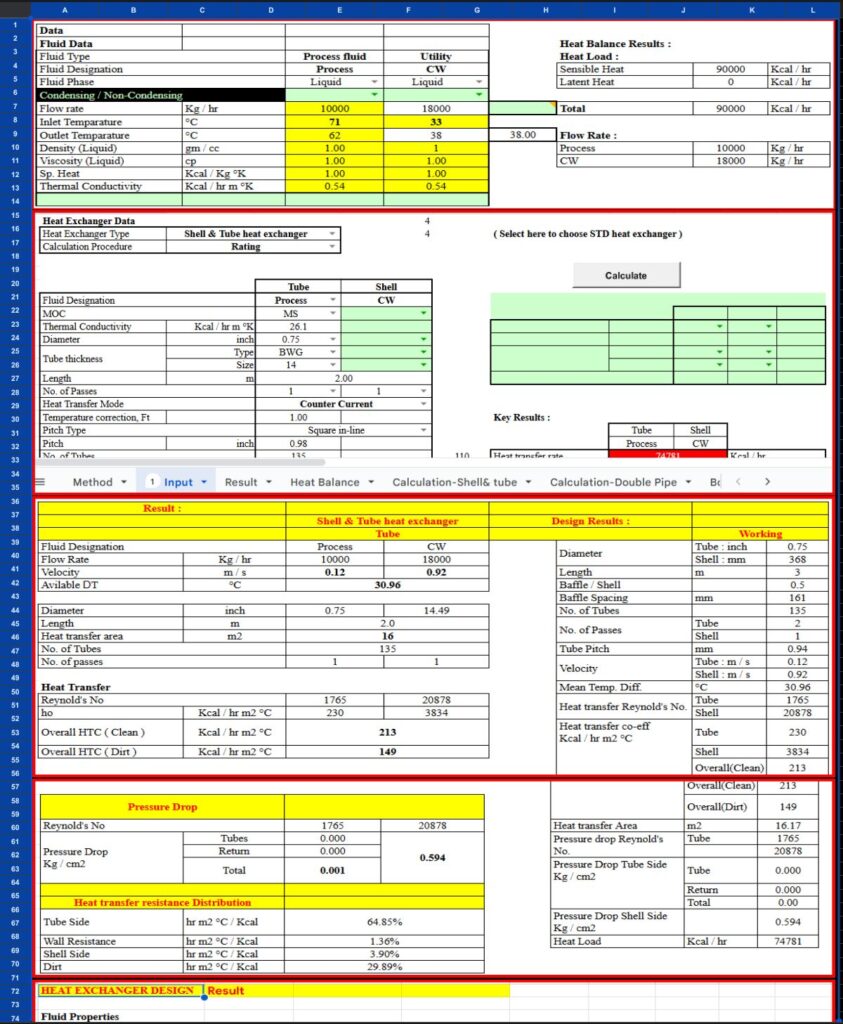
Heat Exchanger Design HE000111
And if mass balance is the piece you still need before the heat balance makes sense, that workbook follows the same validated structure.
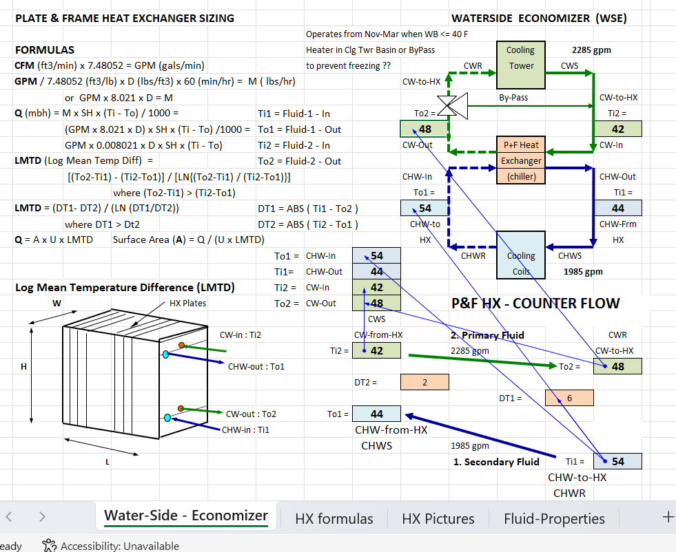
PLATE & FRAME HEAT EXCHANGER SIZING image
FAQ
Why is jacket design duty higher than reaction duty? Because the jacket has to handle more than steady-state reaction heat — start-up sensible heating, control margin, and ambient losses all add to the required duty. A 10–20% margin above reaction duty is typical, depending on insulation and start-up profile.
Why correct the LMTD for a jacket instead of using it directly? Most jackets (annular, half-pipe coil) don’t achieve true counter-current flow, so the ideal LMTD overstates the effective driving force. The correction factor F brings it down to a realistic value — skipping it leads to undersized heat transfer area.
What closure error is acceptable for a process heat balance? Under 5% is the general threshold for issuing a design package. Above that, go back through every stream until you find the gap — it’s almost always a missing or mis-mapped heat term, not measurement noise.
Does pinch analysis matter for small batch reactors? Yes, if there’s any feed stream that needs preheating and any product stream that needs cooling nearby in the process. Even modest recovery (a few hundred kW) adds up fast across multiple batches a day.
Standards Referenced
ASME BPVC Section VIII Div. 1 (jacket pressure design), IS:4503 (Indian standard for process vessels), TEMA (for any auxiliary shell-and-tube exchangers in the cooling loop), ISO 50001 framework (for energy balance reporting where applicable).