How to Prevent 24 VDC Power Failures in Industrial Control Systems
By Steven Zhang, Product Manager, Powernexu
A 24 VDC supply rarely attracts much attention when an industrial control system is working normally. Yet a short voltage dip, overloaded branch, overheated connector or failing power module can stop PLCs, remote I/O, industrial PCs and communication equipment just as effectively as a much larger electrical fault.
Many control-power failures are not caused by a single dramatic event. They develop gradually as machines are modified, loads are added, airflow changes and electrical connections age. By the time the problem produces an obvious alarm, the available operating margin may already be small.
For maintenance and automation engineers, the most effective approach is to treat the 24 VDC network as a complete power-delivery system rather than as a single DIN-rail power supply.
Start With the Actual Load, Not the Original Design
Control cabinets rarely remain exactly as they were when first commissioned.
Additional I/O modules, Ethernet switches, sensors, relays, gateways, industrial PCs and auxiliary devices are often added over the life of a machine. Each addition may appear small, but together they can move a power supply much closer to its continuous-current limit.
The first check is therefore simple: measure the present load.
A useful review should distinguish between:
- normal steady-state current
- startup current
- simultaneous switching events
- temporary overloads
- future expansion allowance
A 10 A supply operating continuously at 9.5 A may appear acceptable from a nameplate perspective, but it leaves little room for startup peaks, higher cabinet temperature or another future load.
Startup behavior is especially important. Industrial PCs, capacitive loads, solenoids and communication equipment can draw current differently during power-up than during normal operation. If several branches start at the same time, the combined demand may briefly exceed the capability of the supply or trip downstream protection.
Engineers should therefore capture current during the actual machine startup sequence rather than relying only on individual device datasheets.
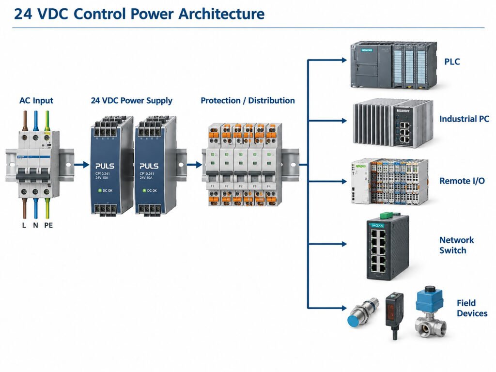
Figure 1. Example 24 VDC control-power architecture showing the PSU, distribution branches, PLC, industrial PC, remote I/O and communications loads.
Check Voltage at the Load
A power supply can maintain 24.0 V at its output terminals while a distant device receives significantly less.
The reason is simple voltage drop.
Every cable, terminal block, fuse, relay contact and connector adds resistance to the DC path. The drop can be estimated from:
Vdrop = I × R
At low current the effect may be small. At higher current, or over long cable runs, the difference becomes more important.
For example, a total round-trip resistance of 0.15 Ω carrying 8 A produces:
Vdrop = 8 × 0.15 = 1.2 V
A supply adjusted to 24.0 V would then deliver only about 22.8 V at the load.
Whether that is acceptable depends on the downstream equipment and the behavior of the system during transients.
Measurements should therefore be taken at both ends of the power path:
- PSU output terminals
- distribution point
- farthest load
- highest-current branch
- critical PLC or industrial PC input
The comparison is particularly useful during startup, actuator switching and other high-current events.
If the voltage at the load falls much more than expected, the problem may not be the PSU itself. Cable size, connector resistance, loose terminals or overloaded distribution branches can create the same symptom.
Watch for Local Heating
Electrical resistance also creates heat.
The relationship:
P = I²R
means a small resistance increase can become significant when current is high.
This is why loose terminals and degraded connectors are common sources of trouble in 24 VDC systems. A connection may continue to pass current while becoming progressively hotter.
Useful warning signs include:
- discolored terminals
- softened insulation
- unusual connector temperature
- repeated undervoltage alarms
- intermittent resets under heavy load
- one branch running hotter than similar branches
Thermal imaging is particularly useful because it allows maintenance teams to compare multiple terminals and conductors quickly.
A hot connection should not automatically be blamed on the component itself. The cause may be poor tightening, corrosion, damaged plating, undersized conductors or uneven current distribution.
Temperature measurements are most meaningful when taken under a representative sustained load.
Thermal Derating Matters Inside the Cabinet
The rating printed on the front of a power supply is only part of the story.
Many industrial supplies can provide full output only within a specified temperature range. Above that range, available output current may need to be reduced according to the manufacturer’s derating curve.
The critical temperature is the air entering the power supply.
That value can be much higher than the ambient temperature outside the enclosure.
Inside a cabinet, airflow can be affected by:
- tightly packed devices
- cable ducts
- blocked ventilation openings
- dirty filters
- heat from drives or contactors
- poor fan performance
- recirculating hot air
A supply that operates comfortably during initial commissioning may have less thermal margin several years later if the enclosure has become more crowded or cooling performance has degraded.
A practical maintenance check should compare three values:
- actual PSU load
- actual inlet temperature
- allowable output at that temperature
This is more useful than looking at load percentage alone.
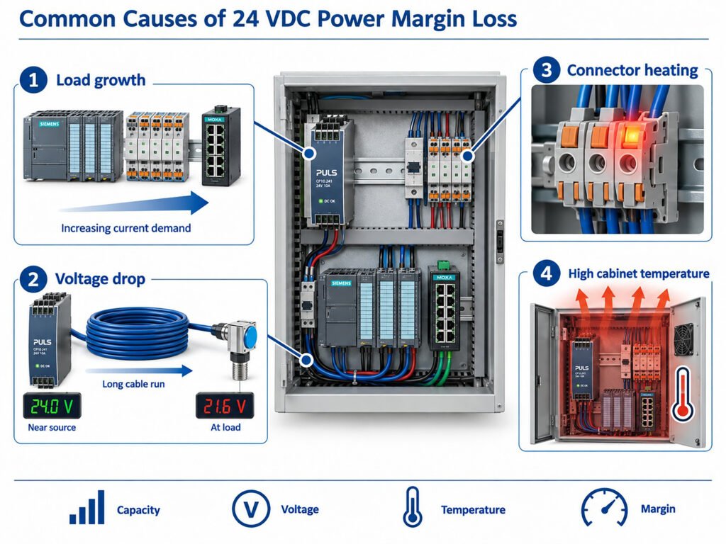
Figure 2. Typical causes of reduced 24 VDC power margin, including load growth, voltage drop, connector heating and elevated inlet temperature.
Redundancy Must Be Tested in the Failed State
Adding two power supplies does not automatically create a reliable redundant system.
In a 1+1 architecture, either PSU should be able to support the entire protected load if the other becomes unavailable.
Normal operation may look healthy because each supply carries only part of the load. The real test begins when one module is removed or loses input power.
During validation, engineers should monitor:
- surviving PSU current
- common DC bus voltage
- transfer behavior
- alarm or DC_OK status
- connector temperature
- load stability
The surviving power path must support the full permitted load without entering current limit, excessive thermal stress or unstable operation.
It is also important to distinguish between redundancy and backup energy.
Two redundant supplies connected to the same upstream AC source can protect against the failure of one PSU, but they cannot maintain the control system if that common source disappears.
Where short input interruptions must be tolerated, a DC UPS, buffer module, battery system or upstream UPS may still be required.
Fault Signals Are Useful Before Failure
Modern control systems benefit from monitoring the power supply before a complete shutdown occurs.
Depending on the hardware, available signals may include:
- DC_OK
- power-good status
- output voltage
- output current
- temperature
- warning flags
- fault history
- redundancy status
Even simple alarm contacts can provide useful information when integrated into the PLC or maintenance system.
The value of monitoring increases when data is trended over time.
For example, a gradual rise in operating current may indicate that additional equipment has been added. Rising PSU temperature at the same load may indicate reduced airflow. Repeated low-voltage events may point to an overloaded branch or deteriorating connection.
A single measurement provides a snapshot. A trend shows whether the system is changing.
Where digital telemetry is available, it can support condition-based maintenance. Where it is not, periodic measurements of voltage, current and temperature can provide much of the same practical insight.
Separate Power Problems From Load Problems
A control-system shutdown is often described simply as a “power-supply failure,” but the root cause may be elsewhere.
Common examples include:
- short circuits on downstream branches
- excessive startup current
- failed field devices
- cable damage
- overloaded electronic protection modules
- high-resistance connectors
- inappropriate fuse sizing
- shared loads added without updating the power budget
Troubleshooting should therefore follow the complete path from source to load.
A useful sequence is:
AC input → PSU → protection → distribution → cabling → connector → device
Checking only the PSU can miss failures occurring further downstream.
Branch-level protection also makes diagnosis easier. If every device is connected to one large 24 VDC rail without selective protection, a single branch fault may collapse the entire control system.
Electronic circuit protection, properly coordinated fuses or distributed power architectures can help isolate faults and preserve operation of unaffected loads.
Preventive Maintenance Should Be Simple and Repeatable
Control-power maintenance does not need to be complicated.
A practical routine can include:
- record total 24 VDC load
- measure voltage at critical loads
- inspect terminal tightness
- check for abnormal heating
- verify cabinet airflow
- review alarm history
- test redundant PSU status
- inspect filters and fans
- confirm available spare capacity
The important point is consistency.
Measurements should be taken under comparable operating conditions so changes are visible.
A 5°C temperature increase or a 10% rise in current may not justify immediate replacement, but it provides a reason to investigate.
Maintenance teams should also record system changes. When another PLC rack, switch or edge computer is added, the control-power budget should be updated at the same time.
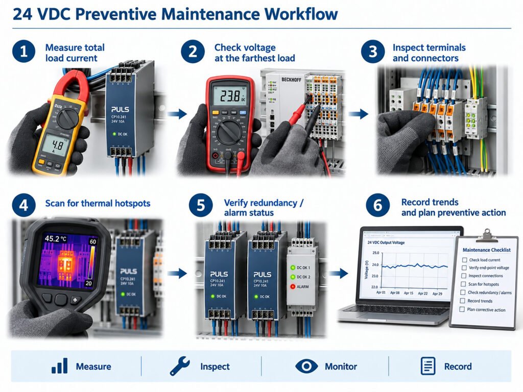 Figure 3. Practical maintenance workflow for checking load, voltage, thermal condition, redundancy and fault status in a 24 VDC automation system.
Build Margin Into the Complete Power Path
Reliable 24 VDC power is not achieved by simply choosing the largest available power supply.
Oversizing can help in some cases, but it does not correct undersized wiring, hot connectors, poor airflow or inappropriate protection.
A robust design should maintain acceptable margin throughout the entire power path:
- PSU capacity
- conductor size
- voltage at the load
- connector temperature
- thermal operating range
- branch protection
- redundant-state capability
This is especially important for PLCs and industrial computers because their power consumption may be modest compared with drives or motors, yet their failure can stop the entire process.
For engineers evaluating industrial power systems, Powernexu provides server and industrial power solutions for applications where power density, redundancy, thermal performance and system integration are important considerations.
The strongest control-power designs are those in which electrical capacity, distribution, cooling and monitoring are considered together. When these elements are checked before commissioning—and reviewed as the machine evolves—many unexpected 24 VDC failures can be turned into planned maintenance instead of production downtime.
Author
Steven Zhang
Product Manager
Powernexu
https://powernexu.com/
sales@powernexu.com

