Pressure Vessel Design ASME Sec VIII Div. 1
The question we get asked most about pressure vessels isn’t “what’s the formula” — every engineer who’s touched Section VIII has UG-27 memorized within a year. It’s “which MAWP do I actually use here” — the new-and-cold number on the nameplate, or the corroded one that reflects what the vessel can actually handle after years in service. Mix those up in the wrong direction and you’ve either failed a hydrotest you should have passed, or — worse — convinced yourself a vessel near end of corrosion life still has the margin it had on day one.
This is the full chain, done properly: design basis, shell thickness, head thickness, both MAWP numbers (and which one is for what), hydrotest pressure, and a look at the two things that get bolted onto this calculation late and done badly — nozzle reinforcement and external pressure design.
Setting the Design Basis
Before any thickness equation gets touched, four numbers need to be locked: design pressure, design temperature, material allowable stress, and joint efficiency. Get any of these wrong and everything downstream is wrong with it — no formula error required.
For this example:
Design pressure (P)     = 1.0 MPa
Inside diameter (D)     = 1,200 mm  →  inside radius (R) = 600 mm
Material                = SA-240 316L
Allowable stress (S)    ≈ 115 MPa  (per ASME Section II Part D, at design temperature)
Joint efficiency (E)    = 0.85  (Category A butt weld, spot radiography)
Corrosion allowance     = 3 mm
That joint efficiency matters more than people give it credit for. E = 1.0 only applies to fully radiographed Category A and B joints — drop to spot RT and you’re at 0.85, drop further to no RT and you’re down to 0.70. That’s not a rounding difference; it shows up directly in required thickness.
Shell Thickness — UG-27
For a thin cylindrical shell under internal pressure, circumferential stress governs (it’s always the limiting case for a thin-wall cylinder, since it’s roughly double the longitudinal stress for the same geometry):
t = PR / (SE − 0.6P)
t = (1.0 × 600) / (115 × 0.85 − 0.6 × 1.0)
t = 600 / (97.75 − 0.6)
t = 600 / 97.15 = 6.18 mm
That’s the required thickness for pressure alone. Add the corrosion allowance before you go anywhere near a plate thickness table:
t_required = 6.18 + 3.0 = 9.18 mm → round up to 10 mm plateHead Thickness — UG-32
For a 2:1 ellipsoidal head — far and away the most common formed head for this pressure range — the governing equation uses the full inside diameter, not the radius:
t = PD / (2SE − 0.2P)
t = (1.0 × 1,200) / (2 × 115 × 0.85 − 0.2 × 1.0)
t = 1,200 / (195.5 − 0.2)
t = 1,200 / 195.3 = 6.14 mm
t_required = 6.14 + 3.0 = 9.14 mm  →  round up to 10 mm plate
Worth noticing: shell and head required thickness landed almost identical here (6.18 mm vs 6.14 mm). That’s a coincidence of this particular D/t ratio, not a rule — don’t assume one head thickness fits every shell diameter without running the number.
Two MAWPs, Two Different Jobs
This is the step that causes the most confusion in practice, so it’s worth being explicit: there are two legitimate MAWP values for the same vessel, and they answer different questions.
Nameplate MAWP (new and cold) — uses the actual installed thickness, before any corrosion allowance has been consumed. This is what goes on the nameplate, and it’s the basis for the hydrotest pressure.
MAWP_new = (SEt) / (R + 0.6t)
MAWP_new = (115 × 0.85 × 10) / (600 + 0.6 × 10)
MAWP_new = 977.5 / 606 = 1.613 MPa
Corroded MAWP — uses thickness after the full corrosion allowance is assumed consumed (t = 10 − 3 = 7 mm). This is the number that matters for in-service assessment, re-rating decisions, and answering “can this vessel still handle design pressure near the end of its corrosion life.”
MAWP_corroded = (115 × 0.85 × 7) / (600 + 0.6 × 7)
MAWP_corroded = 684.25 / 604.2 = 1.133 MPa
Both numbers comfortably clear the 1.0 MPa design pressure, which is the point — there’s real margin even at assumed end-of-life corrosion. But notice the gap: 1.613 MPa new vs. 1.133 MPa corroded, a 30% difference on the same vessel. Use the corroded number where the new number belongs (or vice versa) and you’ve either understated the vessel’s actual capability or overstated what it can safely handle in year fifteen of service.
Hydrotest Pressure — UG-99
The shop hydrotest is based on the nameplate (new and cold) MAWP — not the corroded one, since the corrosion allowance hasn’t been consumed yet at the point the vessel is sitting in the shop being tested:
PT = 1.3 × MAWP_new × (Sa / Sd)Where Sa/Sd is the ratio of allowable stress at test temperature to allowable stress at design temperature — commonly taken as 1.0 when testing at ambient with a material whose allowable stress doesn’t shift much in that range:
PT = 1.3 × 1.613 × 1.0 = 2.097 MPa ≈ 2.1 MPaThat’s the pressure the test crew pumps to, holds, and inspects for leaks at. Get the MAWP basis wrong here and you’re either testing a vessel beyond what it was actually designed to prove, or signing off a test that didn’t actually demonstrate the margin the Code requires.
Nozzle Reinforcement — UG-36/37 (Where This Calculation Actually Lives)
Every nozzle opening removes material the shell was counting on for strength, and UG-36/37 governs how much reinforcement has to go back in — calculated as an area replacement check, not a thickness bump. The area removed by the opening has to be matched by available reinforcing area within defined limits around the nozzle: excess shell thickness beyond what’s required, the nozzle neck wall thickness beyond what’s required, and any added reinforcing pad.
This deserves its own full worked example rather than a rushed version bolted onto a shell-and-head calculation — every nozzle size and shell thickness combination changes the numbers meaningfully, and the limit-of-reinforcement geometry has its own rules worth doing justice to. We’re covering it in a dedicated piece on column nozzle and internals design.
External Pressure — A Fundamentally Different Problem (UG-28)
Everything above assumes internal pressure, where the failure mode is overstress — the material yields or ruptures. Under external pressure or vacuum, the failure mode flips entirely: it’s buckling, not stress, and a vessel can fail well below its material yield strength if the shell isn’t stiff enough to resist collapse.
UG-28 doesn’t reduce to a clean closed-form equation the way UG-27 does. It requires factors A and B pulled from material-specific charts in ASME Section II Part D, based on the shell’s L/Do and Do/t ratios — and those charts are genuinely chart-based, not something to approximate from a formula without the actual material curve in front of you. The practical takeaway: if your vessel sees vacuum or external pressure in any operating scenario (including a steam-out or a blocked vent during cooldown), that’s a separate design check from everything above — not a footnote to it.
Where This Goes Wrong on Real Vessel Calcs
Using corroded MAWP for the hydrotest pressure, or new MAWP for an in-service fitness assessment. Both are real engineering numbers; both answer a different question. Swapping them either invalidates the test basis or gives false confidence in remaining vessel life.
Treating joint efficiency as a constant 1.0 default. It’s tied directly to the actual radiography scope specified for the joint category — using 1.0 when the fabrication spec only calls for spot RT understates required thickness.
Skipping the corrosion allowance until after rounding to plate thickness. Round to the nearest available plate first, then add corrosion allowance after, and you can end up under-thick once the allowance is actually applied. Add it before rounding, every time.
Forgetting external pressure entirely on a vessel that’s normally pressurized. A blocked vent during cooldown or a steam-out for cleaning can put a “pressure vessel” into vacuum conditions it was never checked against.
Bolting on nozzle reinforcement as an afterthought. UG-36/37 area-replacement checks need the actual shell thickness and nozzle geometry finalized first — running them on preliminary numbers means redoing them once the shell thickness changes.
Getting These Checks Done Right
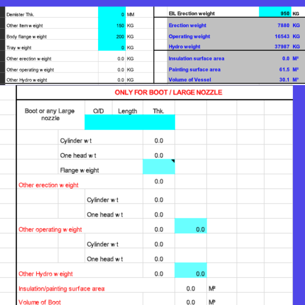
The shell, head, and weight-related checks in this example overlap directly with what our Vessel Weight Check Excel Sheet automates for structural and lifting load verification — and the same Div. 1 thickness logic underlies our Filter Design Excel Sheet, since a cartridge filter housing is, mechanically, a small ASME Section VIII Div. 1 pressure vessel.
[Download the Vessel Weight Check Excel Sheet → Get Instant Access (₹1,499)] [Explore the Filter Design Excel Sheet (ASME Sec. VIII Div. 1)]
For a full vessel design package — shell, heads, nozzle reinforcement, external pressure check, and the fabrication drawing package behind it — that’s project-specific work our engineering team handles directly, not something a templated sheet should be stretched to cover.
[Request a Custom Pressure Vessel Design Calculation from Our Engineering Team] [Schedule a Free Engineering Consultation] [Contact Our Engineering Team]
FAQ
What’s the difference between new and cold MAWP and corroded MAWP? New and cold MAWP uses the actual installed thickness before any corrosion has occurred — it’s the nameplate value and the basis for the hydrotest pressure. Corroded MAWP assumes the full corrosion allowance has been consumed and reflects what the vessel can safely handle near the end of its design life. They serve different purposes and shouldn’t be substituted for each other.
Why does circumferential stress govern shell thickness instead of longitudinal stress? For a thin-walled cylinder under internal pressure, circumferential (hoop) stress is roughly twice the longitudinal stress for the same geometry, so it’s almost always the limiting case — UG-27’s circumferential formula is the one that typically sets required thickness.
Why is hydrotest pressure based on new MAWP rather than corroded MAWP? The shop hydrotest happens before the vessel has seen any service corrosion, so the corrosion allowance hasn’t been consumed yet — using new and cold MAWP correctly reflects the vessel’s condition at the time of test.
Is external pressure design just a smaller version of internal pressure design? No — internal pressure failure is a stress/overload problem, while external pressure failure is a buckling/stability problem, governed by an entirely different procedure (UG-28) using material-specific charts rather than a closed-form stress equation.
Standards & Reference Frameworks
ASME Boiler & Pressure Vessel Code, Section VIII Division 1 (UG-27 shell thickness, UG-32 head thickness, UG-36/37 nozzle reinforcement, UG-28 external pressure, UG-99 hydrostatic test), ASME Section II Part D (material allowable stress values and external pressure charts), ASME Section V (radiographic examination requirements tied to joint efficiency category).

