Installation guide for grid Coupling
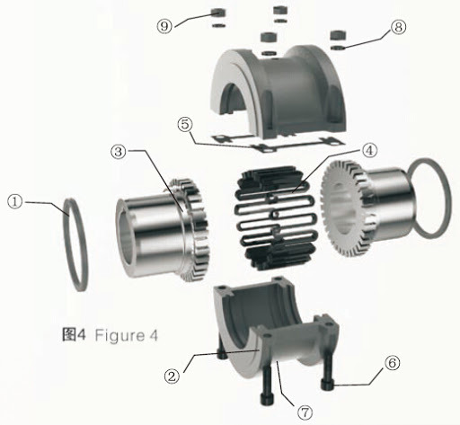
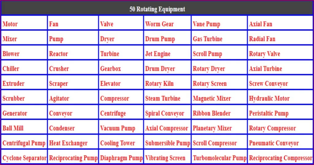
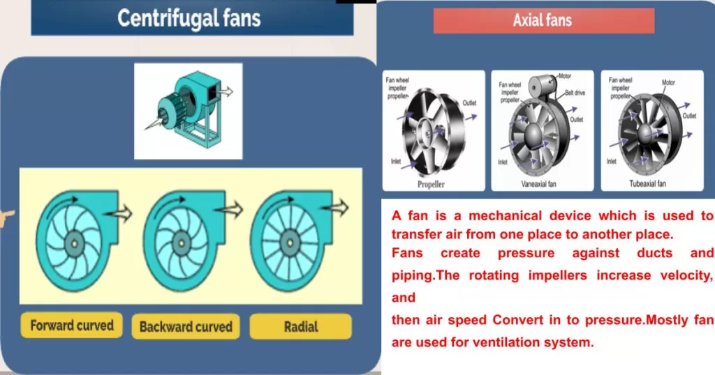
The installation guide for grid coupling provided by the manufacturer, in which torque settings for tightening of the set screws and bolts are also described within it. Some installations guide may contain additional data and dimensional information as well. The grid coupling is the assembly of two shaft hubs, grid, spring, set screw, lubrication, and cover. The grid coupling is ideal for connecting an engine or electric motor to fans, blowers, compressors, pumps, and other devices. Where some dampening of equipment vibration may be required. When the grid coupling can dampen as much as 30 percent of vibration or shock loading.
What are fluid coupling and the advantages of fluid coupling?
Tools required for installation of grid Coupling
Let’s look at the tools by which we will need to perform this installation for grid assembling. These are the following.
- Set screws
- Straight edge
- A putty knife
- Safety glasses
- Dial indicator
- Fine-tooth file
- Vernier calipers
- soft-faced mallet
- Lockout Tagout kit
- Flat blade screwdriver
- Calibrated torque wrench
- Strip of emergency paper
- Sockets for the cover bolts
- Non-flammable cleaning solvent
- A clean cloth and rubberized gloves
- Micrometre to confirm the shaft sizes
What are rigid coupling and an overview of rigid coupling?
Step for installation of grid Couplings
- Before starting this installation process of grid coupling, to ensure each piece of equipment is in safe condition and de-energizes, to prevent any accident. Because due to wrongly start-up or start-up by communication gap, causes could be a danger to the person working on the equipment. This could be possible only following the lockout tag out procedure defined by OSHA.
- When you receive the grid coupling, inspect each component to ensure that there are no visible defects, cracks, or damage from shipping or in manufacturing. You should check the bore size and tolerance before starting the installation. If both shaft and hub have key ways. Then make sure that the appropriate key is ready to use when performing this installation. Ideally, the key should be the same length or slightly longer than the Hub to transmit the maximum allowable torque.
- Then inspect the shaft and should be clean from and up from any Burrs from the keyway or shaft machining. If found, use a fine-tooth file to clean Burrs from the edge of the keyway or large dense in the shaft. Or the zero-size (100 number) sandpaper can be used to clear the shaft of rust or any corrosion.
- Finally, use a cloth with cleaning solvent to clean the shaft and coupling bore. We need to ensure that the surface of the shaft and keyway are clean and free of any dirt. The hub, grid, coupling spring, and cover accessories should also be cleaned to remove coatings used to protect from corrosion and shipping.
- Before installing the hub lubricate both shaft surfaces, coupling seals and place one seal onto each of the shafts, the seals can be stretched over the grid teeth but it is easier to place.
- Put the key in the keyway on both shafts. The key should fit tightly in the keyway without side-to-side movement, the end of the key should line up with the end of the shaft and then install the hub.
- Please note that the grid coupling hub sizes, 10, 20, through 1090 are manufactured with two set screws on each hub. clearance or slip fit Hub should slide onto the shafts without any difficulty.
- The Ring is a major component in grid coupling, place both rings on each shaft. Then install a grid spring, made of steel to connect both shafts and place the spring in the grooves located on the ends of both Hubs. Tossing torque is transmitted between the two hubs through this grid spring.
- Carefully wrapped the grid spring around the hubs, lining up the grids with the hub teeth. The grid spring will need to be stretched slightly and nudged into the slots, using a flat blade screwdriver, finishing with a soft-faced hammer. Regular steel-faced hammers will damage the grid spring and possibly the teeth on the hubs, and should not be used when the grid spring is completely seated. Take a putty knife, preferably one with a soft blade, and smear the remaining grease around the outside of the grid spring.
- To assemble the grid, start by placing one of the covers underneath and aligning the grooves with the seals. Position the two pieces of gasket material onto the corresponding sides of the cover. Next, take the second cover half and align the match marks on the end of the cover with the same end of the coupling to ensure that the recesses in the cover where the fastener nuts will be located are 180 degrees apart. Align the seals and press the cover together, then insert the fasteners with the nuts fitting into the holes. Tighten each bolt until all are assembled, and then tighten each fastener to the specified torque using a torque wrench according to the installation guide.
- Mostly Hub for coupling sizes 1100 and larger size manufactured with interference or Shrink fit, and the installation guide booklet contains details on how to prepare these hubs for installation, regardless of size, keys, and the Hub should be flush with the ends of the shafts.
- During the installation of grid coupling hubs with clearance fit bore and two set screws. Tighten the set screws in both Hubs to the torque specified in the installation guide by the manufacturer With the help of the torque wrench. The use of a torque wrench is very important because the set screws are not tightened enough. The Hub will lose and slide on the shaft during the operation, or the set screws are too tight that can damage the key, shaft, or the hub.
What are flexible coupling and An overview of flexible coupling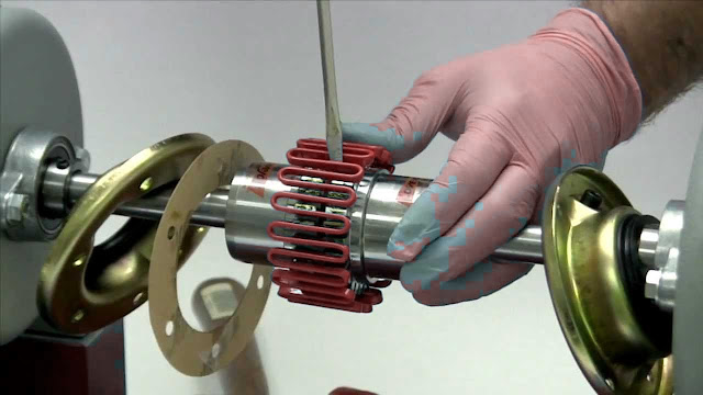
Check alignment of both shaft
- After the installation of both hubs you should proceed to check alignment between each other for both shafts.
- Fix the clamp for check element with a dial gauge, then Carefully move the equipment into position until the distance between the hubs match each other. The hubs Gap listed in the installation guide by the manufacturer within plus or minus 10% can be check with the use of a spacer bar that is the same thickness as the gap or by measuring the separation with Vernier calipers.
- The angular and parallel alignment of the equipment Shafts is critical to the life and performance of The Grid Coupling. the maximum angular misalignment is only one-quarter of a degree and the maximum parallel misalignment is listed in the installation guide. To check the basic alignment, start by laying a straight edge across the major diameter of the hubs. The maximum allowable parallel offset should not exceed the amount for your particular, coupling size as specified in the installation guide.
- The angular and axial alignment can be checked using either a spacer bar, filler gauge, or Vernier calipers to measure the gap between the phases of the hubs. If space permits this measurement should be taken as close as possible to the edge of the grid teeth at four different locations, around the coupling three 90, 180, 270 degrees.
- The difference between any two of these measurements should fall within the range specified by the manufacturer. In the installation guide Under the Heading angular, if the deviation exceeds the angular value specified, you will need to realign the equipment to correct this condition.
Check the alignment by using a dial gauge
- If using a dial indicator to check the parallel alignment by Mount the indicator on the driver shaft with the pointer touching the hub on the opposite shaft. Rotate the shaft with the indicator to the 90 degrees, 180, 270,, and finally 0-degree positions, and make notes of the deviation on the dial. This deviation exceeds the value in the column labeled parallel. You will need to realign the equipment until correct the condition.
Advantages of grid coupling
Grid couplings offer several advantages over other types of couplings, including:
- High torque capacity: Grid couplings can transmit high torque loads, making them suitable for use in heavy-duty applications.
- Absorption of shock loads: The grid coupling’s design allows for the absorption of shock loads, which helps to protect connected equipment from damage due to sudden impact or vibration.
- Misalignment compensation: Grid couplings can compensate for misalignment between connected shafts, which can reduce wear and tear on equipment and increase its lifespan.
- Easy installation and maintenance: Grid couplings are easy to install and maintain, with a simple design that makes it easy to replace damaged parts or adjust alignment as needed.
- Reduced downtime and maintenance costs: Because grid couplings are durable and can compensate for misalignment and shock loads, they can help reduce downtime and maintenance costs by minimizing equipment failure and damage.
- Versatility: Grid couplings are available in a wide range of sizes and configurations, making them suitable for use in a variety of applications across different industries.
Overall, the advantages of grid couplings make them a popular choice for heavy-duty and high-torque applications where reliability and durability are key considerations.
Important instruction to install grid coupling
To install a grid coupling, follow these important instructions:
- Select the correct size and type of coupling based on the application requirements and system specifications.
- Inspect the coupling components for damage or defects before installation, and replace any damaged parts.
- Ensure that the shafts to be connected are clean and free of debris or contamination.
- Align the two shafts to be connected within the manufacturer’s recommended tolerances. Any misalignment beyond recommended tolerances can cause premature wear and failure of the coupling.
- Install the grid assembly onto one shaft, with the correct orientation of the coupling halves and the correct alignment of the grooves with the seals.
- Place the gasket material on the two sides of the cover and press the second cover onto the grid assembly, aligning the match marks to ensure the recesses in the cover are 180 degrees apart.
- Insert the fasteners with the nuts fitting into the holes and tighten each bolt until all are assembled.
- Tighten each fastener to the specified torque using a torque wrench according to the manufacturer’s recommended values.
- Verify that the coupling is operating smoothly and without vibration. Any vibration or noise may indicate misalignment or other issues that need to be addressed.
- Perform regular maintenance and inspections on the coupling to ensure proper operation and prevent premature wear or failure.
Following these important instructions can help ensure the safe and effective installation of a grid coupling, leading to reliable and long-lasting operation of the connected equipment.
To read all about coupling follow the links
- What is coupling and types of coupling – Parts 1
- What is flexible coupling and types of flexible coupling – Parts 2
- What is rigid coupling and types of rigid coupling -Parts 3
- What is fluid coupling and types of fluid coupling – Parts 4
- What is grid coupling and types of grid coupling – Parts 5
- What is gear coupling and types of gear coupling – Parts 6
