Pipeline Design and Drafting
Pipeline design is an important part of any organization to establish or set up a new plant. There are many steps involved to prepare a complete design for a plant. Project designer and draftsman take input from project managers, engineers, and clients to create the framework, plant layout, 3D models, fabrication drawings and specifications for complete process plant and commercial facilities according to user requirements.
The pipeline designing is one of the parts of complete plant design. Pipeline is assembly of pipe, fittings, valves, instruments, and other components. The designers apply knowledge and experience to their specific trade discipline create the framework for Clint and takes inputs from various sources and departments for design plants to meet user requirements.
As per client requirements, drafters and designers follow governmental codes, regulations, safe construction practices, budget limitations, and completion deadlines. and prepared the 3D models and their associated drawings used for construction and fabrication personnel. The all function design team is responsible for designing efficient plant and complete industrial facility.
Design department
Take input from other design department such as civil, structural, instrumentation and electrical and then incorporated throughout the design process. Project design coordination is essential from all design groups and disciplines. Sharing detailed information in a timely manner is important if project completion goals are to be met. As a project progresses through various phases like the design process, site visits of the pipe design team at field to verify like positions, sizes, and locations, existing underground obstructions, structural supports, and mechanical equipment installation location, discussion on pipe routing.
There are some important drawings, documents and specifications that play an important role in designing described below.
- Overview of Pipe Drafting and Design
- Flow Diagrams and Instrumentation
- Codes, Standard and Specifications
- Piping Isometrics and General Arrangement Drawings
- 3D Piping Models and As-Built Drawings
- Project Coordination and Development
- Standard Piping Details
- Equipment and Piping Systems layout
- Valves details
Drawings and documents
Drawings and documents are a very important part of the piping system for selection, fabrication, installation and start up of plants. All departments involved in creation and design of piping documents like root, elevation, sizing and other. These departments are responsible for creating and reviewing the design, drawing and specification like Process, Mechanical, Instrument and Electrical etc. The following most common drawings and documents are prepared and reviewed by the engineering department.
- Process Flow Diagrams (PFD).
- Instrument Process Data Sheet (IPDS)
- Process data sheet (PDS) for equipment.
- Piping and Instrumentation Diagram (P&ID).
- Line List.
Process Flow Diagrams (PFD) (System Flow Diagram – SFD)
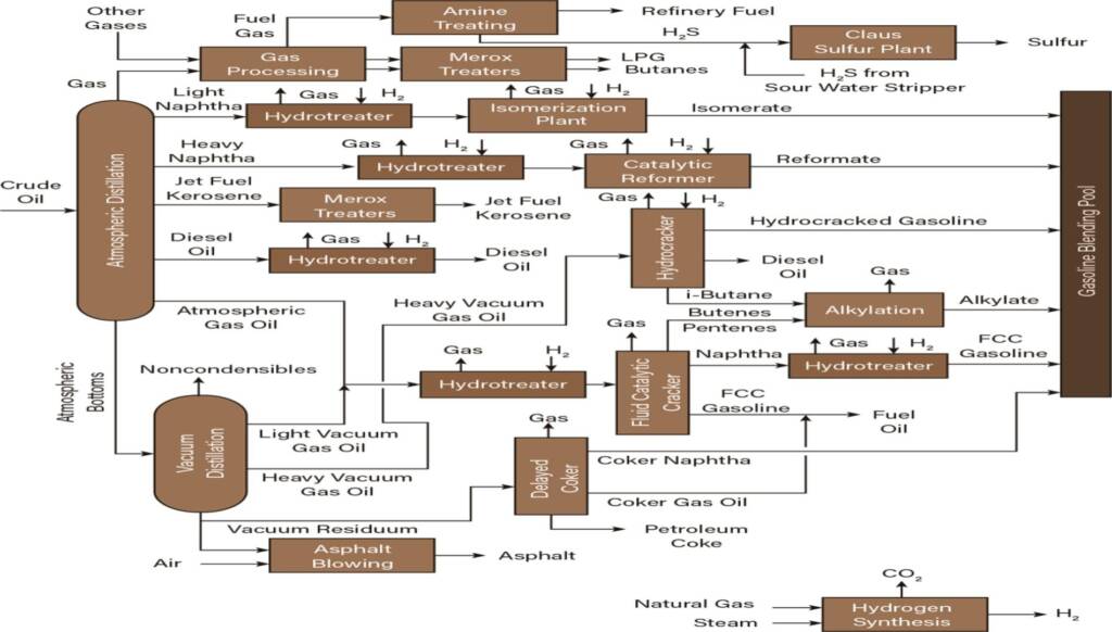
Process flow diagram is a graphical representation of process plant which mentions the primary process flow path. It does not show the minor details of the process, rather it focuses on the equipment, vessel, exchanger, compressor, control valves, flow direction and other instruments. and that represent how the major components of a process plant interconnect to each other for bring the desired output.
It is also used in other sectors such as business administration to understand how other departments of a company can work efficiently in order to achieve their targets like production. Flow diagram was developed by Frank Gilbreth in1921. He introduced it to the American Society of Mechanical Engineers (ASME). The process flow diagram follows as a standard by all industries.
Process flow diagrams represent the connection between major equipment between each other of the process plant. The following process details should be maintained in diagram such as pressure, flow rate, temperature, energy including with other details about fluid like inlet and outlet services fluids its name with details, equipment name with specific identification number. Operating data for equipment in different operating modes, like minimum, normal and maximum. The details which are not included in drawing shall be provided in tabulated format or may be in other format as well.
Some data which are not mentioned in the PDF are as follows: pipe line size, pipe pressure class, schedule number, pipe rating, description and destinations. In a complete PFD diagram following details should be mentioned like as.
- Process equipment and its Piping connection,
- Major equipment symbols, names and identification numbers
- Control valves and its connections
- Interconnection with other systems
- Major bypass and recirculation lines
- System ratings and operational values such as minimum, normal and maximum flow, temperature and pressure
- Composition of fluids
Instrument Process Data Sheet (IPDS)
Instrument Process Data Sheet (IPDS) is an important data sheet for selection of appropriate instrumentation equipment and that is provided by a process engineer or process team. In this data sheet the process team provides basic and critical process information to instrument engineers to verify, float inquiry and procure the instruments equipment.
IPDS required for following equipment selection Temperature elements, Pressure gauge, Level switch, Flow meter, flow switch, Analyzers, and other types (Gauge / Transmitter / Controller / Switch), On/Off Valves and Control Valves. The minimum list of information or data required in the IPDS sheet are as below.
- Instrument Equipment Tag Number, P&ID Number
- Associated Equipment Location and Area Classification
- Service Fluid name, Flow Rate / Liquid level and Properties
- Nature of service fluid like corrosive, flammable, toxic, hot or cold.
- Services fluid Operating & Design Conditions (Pressure & Temperature)
- Alarm Set parameters or Dielectric Constant or specific type of Instruments (If any)
- MOC (Material of Construction), Insulation Requirement and Equipment Specification Requirement
Note – The following things to be confirmed before the selection of instrument equipment: Accuracy, Repeatability, Rangeability, Ease in Installation, Calibration, Turndown Ratio, Density and Compensation. These are important parts that will impact performance for the same. There are some supportive data and documents required to prepare a complete IPDS sheet
- Calculation Report
- Area Classification layout
- Process Design Basis Report
- P&ID and Process Datasheet
- Line-list and its Heat & Mass Balance
- Instrument Specification with Codes & Standards
Process data sheet (PDS) for equipment
Process Data Sheet (PDS) is an important data sheet for selection of appropriate mechanical equipment and that is provided by a process engineer or process team. In this data sheet the process team provides process related details like as.
- Project details including everything location, date and other
- Equipment Tag No and Name, Number quantity of requirement
- Materials compatibility (MOC) with respect to services fluid.
- General arrangement drawing (GAD)
- Service fluid details like Operating Density, Pressure Temperature and flow with (Minium, Normal and Maximum)
Capacity of the equipment like volume, flow, pressure as per equipment requirement. On the basis of details provided in the PDS mechanical design team will prepare the MDS Mechanical data sheet. For every equipment required unique PDS with respect to its feature and data requirement.
Piping and Instrumentation Diagram (P&ID)
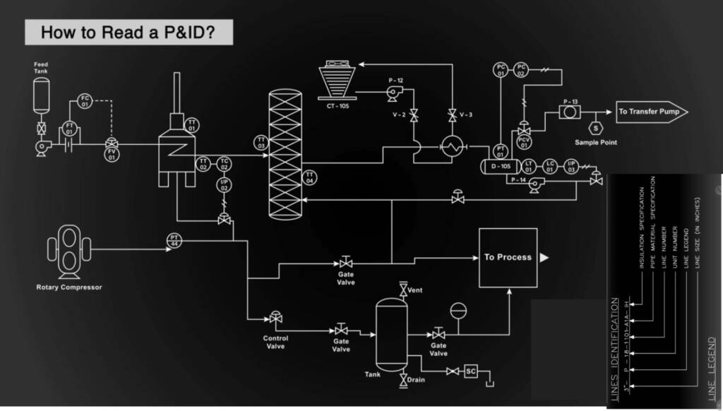
This document covers the general criteria and procedures for the preparation and development of equipment’s Piping, Instrument Diagram and Utility Flow Diagrams for the specific project. Therefore specific items and details in preparing P&IDs of individual units should be confirmed separately from this document.
The units which will be constructed during project execution may be composed of licensed units and non-licensed units. P&IDs and PFD will be prepared by licensors or plant process teams or consultants. The following details should be mentioned in the P&IDs drawing.
- Sheet size and Title Block size sheet shall be used for the drawing as a standard.
- Plant unit names and numbers
- P&ID for Individual Units composing the onsite utility and offsite facilities.
- Utility Flow Diagram covers all distribution flow between onsite and off-site connection.
- P&ID for Process, Utility and Interconnecting Pipe showing the interconnections between the units.
This diagram covers the following information: –
- Fluid Name
- Line Size and Class – Requirement of Insulation and Steam Trace.
- P&ID for Package Unit This is the P&ID which will be submitted by Package Vendor.
- All of the package portions will be blanked out in the main P&ID.
- Legend and General Notes
- P&ID for individual units – Individual section
- Utility distribution
- Process Interconnection Pipe
Notes: (1) Legend and General Notes shall be common for all sections. (2) XXX : Unit Number, Line List
Instrument Department drawing and document Requirements
List of document and drawing required to instrument team for setup complete plant
- Instrument connection Drawings respect to (P&ID).
- Instrument Process Data Sheet (IPDS) reviews PSV, Control Valves, Flow Meters, Level Instruments, Pressure Instruments, Temperature Instruments etc.
- Cable Tray Laying Drawings.
Mechanical Engineering Department
List of document and drawing required to mechanical team for setup of complete plant
- Plot Plan.
- Valve Data Sheets.
- Stress Critical Line List.
- Piping and Support MTO.
- Piping Material Specifications.
- Equipment and Piping Layouts.
- Deliverable Documents and Drawings
- Pipe Rack Layout, Loading and Design.
- Isometric Drawings and its Stress Analysis.
- Equipment Data Sheets for static and rotating.
- Support Register and Special Supports Drawings.
- Nozzle Orientation and Platforms Design Drawings.
- Nozzle Orientation and Platforms Design Drawings.
- Materials Data Sheet (MDS) and Valve Data Sheets (VDS)
- Project Material Take off ( MTO) like Pipe, Fitting, Supports, Equipment, Valve.
- Structural Drawings for RCC, Steel Structure and Technological Structures Loading.
Piping Engineering Drawings and Documents are the documents in which covers, contract and design documents, fabrication details, standard and specifications, operating procedures that are provided by engineering functions like Operation, Process, Mechanical, instruments, electrical, Qualities controls to complete piping projects.
All these were prepared by the related Department. There are many codes and standards available according to the industry and national, and that provide preparation guidance and design documents control but some international standards are often used and in some cases it is mandatory. But the below mentioned list is based on current practices in India. The Process Department will prepare Process Flow Diagrams (PFD), Process Description, Piping and Instrumentation Diagram (P&ID), Process data sheets for equipment, Line List.


