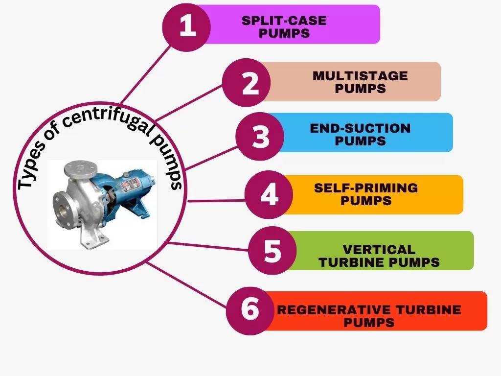
Types of centrifugal pumps and their applications
- Split-Case Pumps
- Multistage Pumps
- End-Suction Pumps
- Self-Priming Pumps
- Vertical Turbine Pumps
- Regenerative Turbine Pumps
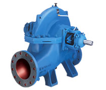
Split-Case Pumps
Split-case pumps are used in applications requiring high flow rates and high head. They are designed with a casing that splits into two halves, making it easy to access the impeller for maintenance. Efficiency ranges typically from 70% to 90%.
Application Split-Case Pumps
Split-Case Pumps are commonly used in applications where high flow rates and high head pressures are required, such as in large-scale water supply and irrigation systems, HVAC systems, and industrial process systems.
Parts of Split-Case Pumps
- Impeller diameter
- Pump casing material
- Shaft material
- Bearing type and arrangement
- Mechanical seal type
- Motor type and rating
- Suction and discharge flange size and rating
- NPSHr requirements
Standards of Split-Case Pumps
- API 610: Standard for centrifugal pumps for petroleum, petrochemical, and natural gas industries.
- ANSI/HI 1.4: Standard for centrifugal pumps for clear liquids.
- NFPA 20: Standard for the installation of stationary pumps for fire protection.
Calculation Example of Split-Case Pumps
A municipal water treatment plant needs to pump 5000 gallons per minute (GPM) of water with a specific gravity of 1.0 from a reservoir at ground level to a water tower located 200 feet above the ground. The piping system has a total equivalent length of 200 feet with 4 elbows and 4 gate valves. The fluid temperature is 60°F and the pump will operate continuously. The pump should have an NPSHr of 10 feet.
Calculation:
- Flow rate: The required flow rate is 5000 GPM.
- Head: The static head is 200 feet. The frictional losses can be calculated using the Darcy-Weisbach equation: f = 0.02 (assumed for the initial calculation)
- ΔP = f * (L / D) * (V^2 / 2g)
- where: L = equivalent length of pipe = 200 + 420 = 280 feet
- D = pipe diameter (assumed to be 8 inches)
- V = fluid velocity = Q / A = 5000 / (π/48^2) = 9.9 ft/s
- g = gravitational constant = 32.2 ft/s^2
- ΔP = frictional losses = 0.02 * (280 / 8) * (9.9^2 / 2*32.2) = 32.5 feet
- Therefore, the total head is 200 + 32.5 = 232.5 feet.
Power Consumption
The required power can be calculated using the following equation:
P = Q * H * ρ * g / η
where: Q = flow rate = 5000 GPM
- H = total head = 232.5 feet
- ρ = fluid density = 62.4 lb/ft^3
- g = gravitational constant = 32.2 ft/s^2
- η = assumed pump efficiency = 85% P = 5000 * 232.5 * 62.4 * 32.2 / (0.85 * 550) = 1484 HP
Therefore, a pump with a minimum of 1484 HP is required.
The materials of construction for the pump should be selected based on the fluid being pumped and the conditions of the application. For this application, a pump with wetted parts made of cast iron, bronze or stainless steel would be suitable.
NPSH: The NPSH required by the pump is 10 feet. The NPSHa can be calculated using the following equation: NPSHa = P1 / (ρ * g) + Z1 – Hs – ΔPvap where
Design selection of Split-Case Pumps
The design selection of Split-Case Pumps involves selecting the appropriate pump size, impeller diameter, materials of construction, and other specifications based on the requirements of the application. Here are the key factors to consider in the design selection of Split-Case Pumps:
- Flow rate and head: The flow rate and head requirements of the application should be carefully determined to select a pump that can meet the performance requirements.
- Impeller diameter: The impeller diameter should be selected to match the required flow rate and head. Larger impeller diameters can handle higher flow rates but may require higher power consumption.
- Materials of construction: The materials of construction for the pump should be selected based on the fluid being pumped and the conditions of the application. Common materials of construction include cast iron, bronze, and stainless steel.
- Motor rating and speed: The motor rating and speed should be selected based on the power requirements of the pump and the availability of the power supply.
- Efficiency: The efficiency of the pump should be considered to ensure that the pump operates at maximum efficiency and minimum operating cost.
- NPSH: The Net Positive Suction Head (NPSH) required by the pump should be considered to ensure that the suction conditions are suitable for the selected pump.
- Mounting and installation: The mounting and installation requirements of the pump should be considered to ensure that the pump can be easily installed and maintained.
- Testing and certification: The pump should be tested and certified according to industry standards such as API 610 and ANSI/HI 1.4 to ensure that the pump meets the required specifications and performance requirements.
Overall, the design selection of Split-Case Pumps should be based on careful consideration of the application requirements, performance specifications, and other factors to ensure that the pump can deliver reliable and efficient performance.
Multistage Centrifugal Pumps
Multistage Centrifugal pumps are used in applications requiring high pressure, such as boiler feedwater, reverse osmosis, and high-pressure water supply. They consist of two or more impellers arranged in series, each impeller adding to the total head. Efficiency ranges typically from 70% to 85%.
Application Multistage Centrifugal Pumps
- Flow rate and head: The flow rate and head requirements of the application should be carefully determined to select a pump that can meet the performance requirements.
- Fluid properties: The properties of the fluid being pumped, including its viscosity, temperature, and corrosiveness, should be considered to ensure that the pump materials of construction are compatible with the fluid.
- NPSH: The Net Positive Suction Head (NPSH) required by the pump should be considered to ensure that the suction conditions are suitable for the selected pump.
- Efficiency: The efficiency of the pump should be considered to ensure that the pump operates at maximum efficiency and minimum operating cost.
- Mounting and installation: The mounting and installation requirements of the pump should be considered to ensure that the pump can be easily installed and maintained.

Part List Selection Codes of Multistage Pump
- Pump Type: Multistage Pump
- Pump Stage: The number of stages required to achieve the desired head.
- Materials of Construction: Common materials include cast iron, bronze, and stainless steel.
- Shaft Seals: The type of shaft seal required, such as mechanical seals or packing.
- Bearing Type: The type of bearing used, such as sleeve or ball bearings.
- Motor Type: The type of motor used, such as standard or explosion-proof.
Standards and Specifications of Multistage Pump
- API 610: This standard provides guidelines for the design, construction, and operation of centrifugal pumps used in the petroleum, petrochemical, and gas industries.
- ANSI/HI 1.4: This standard provides guidelines for the design, construction, and operation of general-purpose centrifugal pumps.
- ISO 5199: This standard provides guidelines for the design, construction, and operation of chemical process pumps.
Calculation of Multistage Pump
- Determine the required flow rate and head: The flow rate and head requirements of the application should be carefully determined to select a pump that can meet the performance requirements.
- Determine the number of stages required: The number of stages required to achieve the desired head can be calculated using the following formula: N = H / h where N is the number of stages, H is the total head required, and h is the head per stage.
- Calculate the efficiency: The efficiency of the pump can be calculated using the following formula: Efficiency = (H * Q) / (3.65 * P * SG * RPM) where P is the power input to the pump, SG is the specific gravity of the fluid, and RPM is the pump speed.
Check the NPSH requirements:
- The NPSH required by the pump should be calculated to ensure that the suction conditions are suitable for the selected pump. Assuming an NPSH required of 3 m, we can check if the available NPSH (NPSHA) is sufficient using the following formula: NPSHA = Ha – Hf – Hs – Hv where Ha is the absolute pressure at the pump suction, Hf is the frictional losses in the suction line, Hs is the static head at the suction, and Hv is the velocity head at the suction.
Overall, the application, part list selection codes, standards, and specifications of Multistage Pumps with calculation should be based on careful consideration of the application requirements, performance specifications, and other factors to ensure that the pump can deliver reliable and efficient performance.
Here is an example specification of a Multistage Pump with calculation:
Application: The pump will be used to transfer water in an industrial process with the following requirements: Flow rate: 80 m3/h, Total head: 300 m, Fluid properties: Water at 20°C and a specific gravity of 1.
Pump Stage: The number of stages required to achieve the desired head can be calculated as: N = H / h = 300 / 60 = 5 stages
Calculate the efficiency: Assuming a pump speed of 2900 RPM, the power input to the pump can be calculated as:
P = (Q * H * SG) / (3.65 * Efficiency) = (80 * 300 * 1) / (3.65 * 0.8) = 686 kW
The efficiency of the pump can be calculated as:
Efficiency = (H * Q) / (3.65 * P * SG * RPM) = (300 * 80) / (3.65 * 686 * 1 * 2900) = 0.86 or 86%
Check the NPSH requirements:
Assuming an NPSH required of 3 m, we can check if the available NPSH (NPSHA) is sufficient using the following formula:
NPSHA = Ha – Hf – Hs – Hv
- where Ha is the absolute pressure at the pump suction,
- Hf is the frictional losses in the suction line,
- Hs is the static head at the suction, and
- Hv is the velocity head at the suction.
Assuming the suction line has a diameter of 150 mm and a length of 10 m, the frictional losses can be calculated as:
Hf = (f * L/D) * (V^2/2g) = (0.02 * 10/0.15) * (4.46^2 / 2 * 9.81) = 0.35 m
Assuming the pump is located at ground level, the static head at the suction is 0 m, and the velocity head at the suction is negligible.
Therefore, the NPSHA is: NPSHA = 101.325 kPa – 0.35 m – 0 m – 0 m = 101.006 kPa Since the NPSHA is greater than the NPSH required, the suction conditions are suitable for the selected pump.
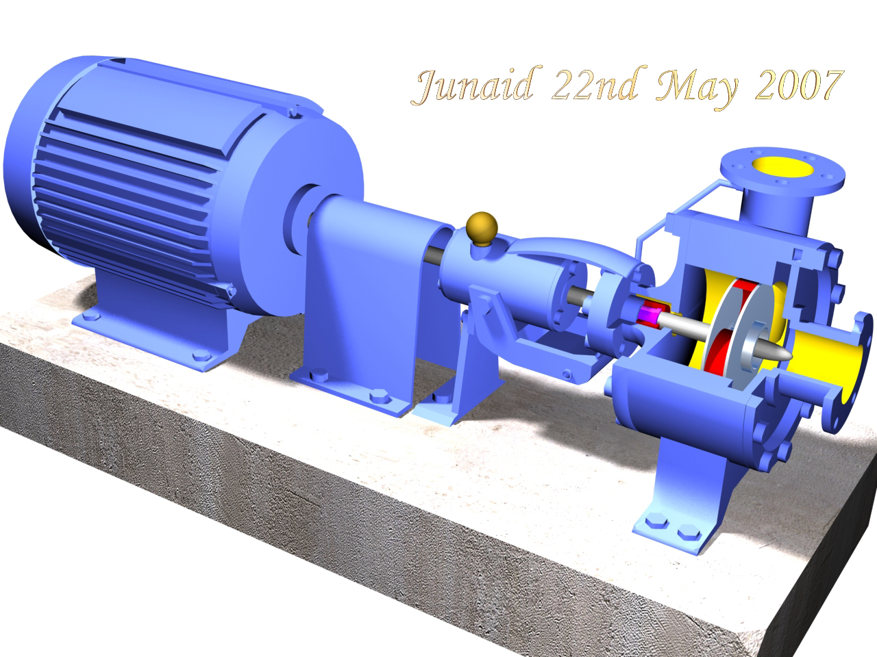
End-Suction Pumps
End-suction pumps are the most common type of centrifugal pump used in commercial and industrial applications. They are simple to install and maintain, have a relatively low cost, and are available in a wide range of sizes and capacities. Efficiency ranges typically from 50% to 90%.
End-Suction Pumps standard
When selecting an End-Suction Pump for a particular application, there are various industry standards and specifications that must be considered to ensure optimal performance and reliability. Here are some of the most important standards and specifications to consider:
- Hydraulic Institute Standards (HI): The Hydraulic Institute is a leading organization in the pump industry that sets standards and guidelines for centrifugal pump design, operation, and maintenance. HI standards cover topics such as pump performance, NPSH requirements, and mechanical seals. These standards are a valuable resource for selecting and specifying End-Suction Pumps.
- American National Standards Institute (ANSI): ANSI is a non-profit organization that develops and publishes voluntary consensus standards for various industries, including pumps. ANSI standards cover topics such as pump dimensions, materials, and performance requirements. ANSI pump standards specify the dimensional and operational criteria that must be met to ensure compatibility with other system components.
- National Fire Protection Association (NFPA): The NFPA publishes standards for fire pumps used in commercial and industrial applications. NFPA standards specify requirements for pump performance, construction, and installation to ensure that fire pumps can deliver water to fire protection systems when needed.
- American Petroleum Institute (API): The API sets standards and specifications for pumps used in the oil and gas industry. API standards cover topics such as pump construction, materials, and performance requirements. API pumps are designed to withstand the harsh conditions and demanding applications encountered in the oil and gas industry.
Example and Calculation of End-Suction Pump
A chemical processing plant needs to pump 50 gallons per minute of a corrosive liquid with a specific gravity of 1.2 and a viscosity of 100 cP from a storage tank on the ground floor to a processing tank on the second floor located 20 feet above the ground floor. The piping system has a total equivalent length of 100 feet with 2 elbows and 2 gate valves. The fluid temperature is 80°F and the pump will operate continuously. The pump should have a NPSHr of 10 feet.
Calculation:
- Flow rate: The required flow rate is 50 gallons per minute.
- Head: The static head is 20 feet. The frictional losses can be calculated using the Darcy-Weisbach equation:
- f = 0.02 (assumed for the initial calculation)
- ΔP = f * (L / D) * (V^2 / 2g) where:
- L = equivalent length of pipe = 100 + 220 = 140 feet
- D = pipe diameter (assumed to be 2 inches)
- V = fluid velocity = Q / A = 50 / (π/42^2) = 7.95 ft/s
- g = gravitational constant = 32.2 ft/s^2
- ΔP = frictional losses = 0.02 * (140 / 2) * (7.95^2 / 2*32.2) = 8.1 feet Therefore, the total head is 20 + 8.1 = 28.1 feet.
Power:
The required power can be calculated using the following equation:
- P = Q * H * ρ * g / η where:
- Q = flow rate = 50 GPM
- H = total head = 28.1 feet
- ρ = fluid density = 1.2 * 62.4 = 74.88 lb/ft^3
- g = gravitational constant = 32.2 ft/s^2
- η = assumed pump efficiency = 75% P = 50 * 28.1 * 74.88 * 32.2 / (0.75 * 550) = 27.5 HP
- Therefore, a pump with a minimum of 27.5 HP is required.
Materials: The materials of construction for the pump should be selected based on the fluid being pumped and the conditions of the application. For this application, a pump with wetted parts made of corrosion-resistant materials such as stainless steel or high-performance plastics like PTFE or PVDF should be used.
NPSH:
The NPSH required by the pump is 10 feet. The NPSHa can be calculated using the following equation:
- NPSHa = P1 / (ρ * g) + Z1 – Hs – ΔPvap
- where: P1 = pressure at the pump inlet = atmospheric pressure (assumed to be 14.7 psi)
- Z1 = height of pump inlet = 0 feet
- Hs = static head = 20 feet
- ΔPvap = vapor pressure of the fluid being pumped = assumed to be negligible
- NPSHa = 14.7 / (74.88 * 32.2) + 0 – 20 – 0 = -0.8 feet (negative value means that cavitation will occur) Therefore, the pump must be installed with a NPSH available of at least 10.8 feet.
Based on these calculations, an End-Suction Pump with the following specifications would be.
Self-Priming Pumps
Self-priming pumps are used in applications where the pump needs to be located above the liquid being pumped. They are designed with a special impeller that creates a vacuum to draw the liquid up into the pump. Efficiency ranges typically from 50% to 70%.
Self-priming pump Application:
Self-priming pumps are commonly used in applications where the pump must be able to create suction and lift fluid from a lower level, without the need for additional priming equipment or manual intervention. Some common applications for self-priming pumps include:
- Water transfer and circulation – Self-priming pumps are often used in applications where water needs to be moved from one location to another, such as irrigation systems, swimming pool pumps, and fountain pumps.
- Sewage and wastewater treatment – Self-priming pumps can handle solids and viscous fluids, making them ideal for use in sewage and wastewater treatment facilities.
- Chemical processing – Self-priming pumps can handle a wide range of chemicals and fluids, making them useful in chemical processing and industrial applications.
- Agriculture – Self-priming pumps are used in agricultural applications for irrigation, crop spraying, and transferring water between tanks or ponds.
- Oil and gas – Self-priming pumps can be used in the oil and gas industry for applications such as transfer and circulation of crude oil, water injection, and well service operations.
- Food and beverage – Self-priming pumps can be used in the food and beverage industry for applications such as filling and packaging, transferring liquids between tanks, and pumping viscous fluids like syrup or cream.
Part List of self-priming pump
- Casing: Cast iron
- Impeller: Cast iron
- Shaft: Carbon steel
- Bearings: Ball type, grease lubricated
- Seals: Mechanical
- Motor: NEMA standard, TEFC
Calculation of self-priming pump
- Flow rate: 150 GPM
- Head: 80 feet
- Viscosity: 1 cP
- Specific gravity: 0.9
- Temperature: 70°F
Determine the NPSH required (NPSHR)
- NPSHR = (K * V^2) / (2 * g) Assume a K value of 1.5 and a velocity of 6 feet per second.
NPSHR = (1.5 * 6^2) / (2 * 32.2) = 0.70 feet
Calculate the NPSH available (NPSHA)
- NPSHA = Ha – Hf – Hv – Hs
- Assume an absolute pressure at the suction of 14.7 psi (atmospheric pressure), a frictional loss in the suction line of 3 feet, a static head at the suction of 5 feet, and a velocity head at the suction of 1 foot.
- NPSHA = (14.7 * 2.31) – 3 – 1 – 5 = 26.17 feet
- Check if the available NPSH is greater than the required NPSH. If the available NPSH is less than the required NPSH, the pump may experience cavitation, which can cause damage to the impeller and decrease the efficiency of the pump.
- Since the NPSHA (26.17 feet) is greater than the NPSHR (0.70 feet), the pump selection is suitable for the given application.
- Determine the required horsepower of the pump using the following formula:
- Horsepower = (Flow rate * Head * Specific gravity) / (3960 * Efficiency)
- Assume an efficiency of 75%.
- Horsepower = (150 * 80 * 0.9) / (3960 * 0.75) = 2.29 horsepower
- Select a suitable motor for the pump. Based on the horsepower calculated, a 3 horsepower motor would be appropriate.
- Check the manufacturer’s data for the maximum recommended suction lift for the selected pump. Assuming the maximum recommended suction lift is 15 feet, and the static head at the suction is 5 feet, the maximum allowable suction lift for the pump would be 10 feet.
- Check the manufacturer’s data for any other specific requirements or limitations for the selected pump, such as maximum operating temperature or material compatibility.
Note: The calculation for self-priming pumps can vary depending on the manufacturer and specific pump design. It is important to consult the manufacturer’s data and specifications for accurate and reliable results.
Vertical Turbine Pumps
Vertical turbine pumps are used in applications where the pump needs to be installed in a deep well or a sump. They are designed with a long shaft that connects the impeller to the motor above ground. Efficiency ranges typically from 70% to 90%.
Part List Selection Codes Vertical Turbine Pumps:
- Pump Type: Vertical Turbine Pump
- Pump Stage: The number of stages required to achieve the desired head can be calculated as: N = H / h = 150 / 30 = 5 stages
- Materials of Construction: Stainless steel AISI 304
- Shaft Seals: Mechanical seals
- Bearing Type: Thrust bearings and sleeve bearings
- Motor Type: Submersible motor
Standards and Specifications Vertical Turbine Pumps:
- API 610: This standard will be used as a guideline for the design, construction, and operation of the pump.
- AWWA B100: This standard will be used as a guideline for the design, construction, and installation of vertical turbine pumps for water supply service.
- Hydraulic Institute Standards for Vertical Turbine Pumps (HI 2.1-2.5): This standard will be used as a guideline for the design, construction, and operation of the pump.
- National Electrical Manufacturers Association (NEMA) MG 1: This standard will be used as a guideline for the design, construction, and installation of the motor.
Calculation Vertical Turbine Pumps
Application: The pump will be used to transfer water from a well to a storage tank with the following requirements:
- Flow rate: 50 m3/h
- Total head: 150 m
- Fluid properties: Water at 20°C and a specific gravity of 1
- Determine the required flow rate and head: The required flow rate is 50 m3/h, and the required head is 150 m.
- Determine the number of stages required: The number of stages required to achieve the desired head can be calculated as: N = H / h = 150 / 30 = 5 stages
- Calculate the efficiency: Assuming a pump speed of 2900 RPM, the power input to the pump can be calculated as: P = (Q * H * SG) / (3.65 * Efficiency) = (50 * 150 * 1) / (3.65 * 0.8) = 318 kW
- The efficiency of the pump can be calculated as: Efficiency = (H * Q) / (3.65 * P * SG * RPM) = (150 * 50) / (3.65 * 318 * 1 * 2900) = 0.77 or 77%.
- Determine the bowl assembly: The bowl assembly will consist of 5 stages, each with a bowl diameter of 8 inches, and made of stainless steel AISI 304.
- Determine the motor: The submersible motor will be a 350 HP, 6-pole motor with a voltage rating of 460 V, and a frequency of 60 Hz.
- Determine the column pipe: The column pipe will be made of stainless steel AISI 304, with a diameter of 8 inches and a length of 9 meters.
- Check the NPSH requirements: Assuming an NPSH required of 3 m, we can check if the available NPSH (NPSHA) is sufficient using the following formula: NPSHA = Ha – Hf – Hs – Hv where Ha is the absolute pressure at the pump suction, Hf is the frictional losses in the suction line, Hs is the static head at the suction, and Hv is the velocity head at the suction. Assuming the suction line has a diameter of 200 mm and a length of 10 m, the frictional losses can be calculated as: Hf = (f * L/D) * (V^2/2g) = (0.02 * 10/0.2) * (2.98^2 / 2 * 9.81) = 0.15 m Assuming the pump is located at a depth of 20 m, the static head at the suction is 20 m, and the velocity head at the suction is negligible. Therefore
Regenerative Turbine Pumps
Regenerative turbine pumps are used in applications requiring high pressure and low flow rates, such as in refrigeration systems and small-scale water treatment plants. They are designed with a small impeller that rotates at high speed within a small casing. Efficiency ranges typically from 50% to 80%.
Overall, the efficiency of a centrifugal pump depends on various factors such as impeller design, fluid properties, and system requirements. It’s essential to select the right pump for a particular application to ensure optimal efficiency and performance.
Regenerative turbine pumps, also known as peripheral pumps, are commonly used in low-flow, high-head applications such as in the chemical and pharmaceutical industries, as well as in heating and cooling systems.
Selection of a regenerative turbine pump
The selection of a regenerative turbine pump involves several factors, including the flow rate, head, viscosity, specific gravity, and temperature of the fluid being pumped. The following is a general guide for selecting and specifying a regenerative turbine pump.
Part List:
- Casing: Cast iron, ductile iron, or bronze
- Impeller: Bronze or stainless steel
- Shaft: Stainless steel
- Bearings: Ball or sleeve type, grease or oil lubricated
- Seals: Mechanical or packing gland
- Motor: NEMA standard, open drip-proof, TEFC or explosion-proof
Calculation: The performance of a regenerative turbine pump can be determined by the pump curve, which shows the relationship between flow rate and head. The pump curve can be generated experimentally by measuring the head and flow rate at various operating points or can be obtained from the manufacturer’s data.
Here is an example of a calculation for a regenerative turbine pump:
Application:
- Flow rate: 100 GPM
- Head: 500 feet
- Viscosity: 30 cP
- Specific gravity: 1.1
- Temperature: 200°F
Calculation:
- Determine the BEP of the pump from the pump curve provided by the manufacturer. The BEP is the point of maximum efficiency and is usually the desired operating point for the pump.
- Assume that the BEP of the pump is at 80 GPM and 475 feet of head.
- Calculate the power required by the pump using the following formula:
- Power = (Head * Flow rate * Specific gravity) / (3960 * Efficiency * Motor efficiency)
- Assume an efficiency of 70% and a motor efficiency of 85%.
- Power = (500 * 100 * 1.1) / (3960 * 0.7 * 0.85) = 21.3 horsepower
- Determine the NPSHR of the pump from the manufacturer’s data or by using the following formula:
- NPSHR = (K * V^2) / (2 * g)
- Assume a K value of 2.0 and a velocity of 4 feet per second.
- NPSHR = (2.0 * 4^2) / (2 * 32.2) = 0.99 feet
- Calculate the available NPSH using the following formula:
- NPSHA = Ha – Hf – Hv – Hs
- Assume an absolute pressure at the suction of 20 psi, a frictional loss in the suction line of 5 feet, a static head at the suction of 10 feet, and a velocity head at the suction of 1 foot.
- NPSHA = (20 * 2.31) – 5 – 1 – 10 = 27.2 feet
- Check if the available NPSH is greater than the required NPSH. If the available NPSH is less than the required NPSH, the pump may experience cavitation, which can cause damage to the impeller and decrease the efficiency of the pump.
Since the NPSHA (27.2 feet) is greater than the NPSHR (0.99 feet), the pump selection is suitable for the given application.
Note: The calculation for regenerative turbine pumps can vary depending on the manufacturer and specific pump design. It is important to consult the manufacturer’s data and specifications for accurate and reliable results.
- What is Gear Pump it’s Works and Applications
- Centrifugal Pump
- Cavitation in centrifugal pump
- Basics of reciprocating pump
- Types of Pumps: A Comprehensive Guide
- Centrifugal pump characteristic curves
- Troubleshooting of centrifugal pump New 1
- Characteristics of positive displacement pump
- Basic use of wearing rings in centrifugal pump

