What is the balance drum?
The term “balance drum” is not commonly used in relation to pumps. However, it is possible that you are referring to a component called a “balance drum” in specific types of pumps called multistage centrifugal pumps.
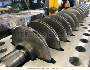
In multistage centrifugal pumps, the balance drum is a device used to balance the axial thrust generated by the impellers. Axial thrust is the force that pushes the rotor of the pump along the axis of rotation. This thrust is caused by the pressure difference across the impellers as the fluid flows through them.
The balance drum is typically located between the high-pressure and low-pressure stages of the pump. It consists of a drum-shaped chamber with an open end and is connected to the pump’s discharge pipe. The drum is partially filled with the pumped fluid. As the fluid flows from the high-pressure stage to the low-pressure stage, it enters the balance drum, and the axial thrust is balanced by the pressure on the fluid in the drum. The pressure in the drum acts in the opposite direction to the axial thrust, reducing its effect on the rotor and minimizing the bearing load.
The balance drum helps to improve the stability and reliability of multistage centrifugal pumps by reducing the axial forces exerted on the pump’s components. By minimizing the axial thrust, the balance drum helps to prolong the life of the pump and prevent excessive wear on the bearings and other critical parts.
What is the balance disk?
Balance disk in centrifugal pump
In the context of pumps, a balance disk is a component used in certain types of centrifugal pumps to balance axial thrust. Axial thrust is the force that pushes the rotor along the axis of rotation, and it is generated due to the pressure difference across the impellers as the fluid flows through them.
A balance disk is a circular disk that is typically installed on the end of the pump shaft or on a separate shaft extension. The balance disk is designed to rotate with the shaft and is located in a chamber filled with fluid, usually the pumped fluid itself.
The balance disk works based on the principle of hydrodynamic balancing. When the pump is operating, the fluid pressure on one side of the disk is different from the pressure on the other side. This pressure difference creates a force that acts on the disk. The shape and positioning of the balance disk are carefully designed to generate a force that counteracts the axial thrust.
By using a balance disk, the axial thrust is minimized, reducing the load on the pump’s bearings and improving the overall stability and efficiency of the pump. The balance disk can be adjusted or designed with specific characteristics to achieve the desired balancing effect based on the pump’s operating conditions.
It’s worth noting that balance disks are commonly used in certain types of pumps, such as multi-stage, high-pressure pumps or large vertical pumps, where the axial thrust can be significant. However, not all pumps utilize balance disks, as their necessity and design depend on the specific pump configuration and operational requirements.
What is balance piston?
A balance piston is a component commonly used in reciprocating pumps and compressors to counteract the axial thrust generated during operation.
In reciprocating machines, such as pumps or compressors, the piston moves back and forth within a cylinder. This reciprocating motion generates axial forces known as axial thrust. Axial thrust can cause excessive wear on the cylinder walls, piston rings, and other components, leading to reduced efficiency and potential damage.
To counteract the axial thrust, a balance piston is utilized. The balance piston is typically located on the opposite side of the main piston within the cylinder. It is a smaller piston that operates in sync with the main piston but in the opposite direction. When the main piston moves in one direction, the balance piston moves in the opposite direction, creating a balancing effect.
The balance piston is connected to a balancing chamber or a pressure equalization system. The pressure in the balancing chamber is controlled to create a force that counteracts the axial thrust generated by the main piston. By balancing the axial forces, the wear on the cylinder walls and other components is reduced, improving the efficiency and longevity of the reciprocating machine.
The design and implementation of balance pistons can vary depending on the specific application and operating conditions of the reciprocating machine. The size, shape, and configuration of the balance piston, as well as the pressure control mechanism, are tailored to achieve optimal balancing performance for a given pump or compressor.
What is axial thrust bearing?
Thrust bearing
A thrust bearing is a type of bearing specifically designed to handle axial loads, or thrust, in a rotating shaft. Unlike radial bearings, which primarily support radial loads perpendicular to the shaft, thrust bearings are intended to counteract forces parallel to the shaft’s axis.
Thrust bearings typically consist of two main components: a bearing housing and a set of rolling elements. The housing, often called a race or washer, contains grooves or tracks that guide the rolling elements. The rolling elements, which can be balls, cylinders, or tapered rollers, are positioned between the housing’s tracks. They facilitate smooth rotation while distributing and balancing the axial load.
The design and configuration of thrust bearings can vary depending on the specific application and load requirements. Some thrust bearings incorporate a separate thrust collar or washer, which provides additional support and alignment for the rotating shaft.
Thrust bearings are commonly used in various applications, including pumps, turbines, gearboxes, and automotive transmissions, where axial loads need to be effectively managed to ensure smooth and efficient operation.
What is flange drum and stepped drum?
It seems that both the flange drum and stepped drum are components that are utilized in conjunction with a balance drum and balance disk. These drums are designed and configured based on the hub leeway, which refers to the allowable clearance or tolerance between the rotating components, such as the drum, shaft, or disk.
The hub leeway is an important consideration in the design and assembly of these components. It ensures that there is sufficient clearance to accommodate any thermal expansion, misalignment, or dynamic forces that may occur during operation. By allowing for a certain amount of movement or play, the hub leeway helps to prevent excessive friction, wear, or binding between the rotating parts.
The specific design and configuration of the flange drum and stepped drum will depend on the requirements of the application and the desired hub leeway. These components may feature flanges, stepped surfaces, or other design elements that facilitate the proper clearance and alignment between the rotating parts.
What is the difference between a balance disk and a balance drum?
The main difference between a balance disk and a balance drum lies in their shapes and configurations, as well as their specific applications within pumps or other rotating machinery.
- Balance Disk:
- Shape: A balance disk is typically a circular disk-like component.
- Placement: It is installed on the end of the pump shaft or on a separate shaft extension.
- Function: The balance disk operates based on hydrodynamic balancing. The pressure difference on either side of the disk generates a force that counteracts axial thrust.
- Usage: Balance disks are commonly used in centrifugal pumps or compressors to balance axial thrust and reduce bearing loads.
- Balance Drum:
- Shape: A balance drum is drum-shaped, resembling a cylindrical chamber with one open end.
- Placement: It is usually located between the high-pressure and low-pressure stages of a multistage centrifugal pump.
- Function: The balance drum acts as a reservoir, partially filled with the pumped fluid, to balance axial thrust. The pressure in the drum opposes and reduces the effect of axial thrust on the rotor.
- Usage: Balance drums are specifically employed in multistage centrifugal pumps to minimize axial forces and prolong the pump’s life.
While both balance disks and balance drums serve the purpose of balancing axial thrust in rotating machinery, their designs and mechanisms differ. Balance disks use pressure differentials on either side of a circular disk, while balance drums utilize fluid pressure within a drum-shaped chamber to counteract axial forces.
Thrust load with example and calculation
Thrust load, also known as axial load, refers to the force that acts parallel to the axis of rotation in a machine or component. It is crucial to consider thrust load when designing or analyzing systems that involve axial forces, such as pumps, turbines, or bearings.
To provide an example and calculation of thrust load, let’s consider a simple scenario:
Example: Suppose we have a centrifugal pump with a single impeller. The impeller is designed to pump water with a flow rate of 1000 liters per minute (LPM) and a discharge pressure of 10 bar. We want to determine the thrust load generated by the impeller.
Calculation: To calculate the thrust load, we need to consider the pressure difference across the impeller and the impeller area.
Step 1: Calculate the pressure difference (∆P): ∆P = Discharge Pressure – Suction Pressure
Assuming the suction pressure is atmospheric (0 bar), the pressure difference (∆P) would be: ∆P = 10 bar – 0 bar = 10 bar
Step 2: Determine the impeller area (A): The impeller area depends on its design and geometry. Let’s assume the impeller has a diameter of 10 cm.
The impeller area (A) can be calculated using the formula for the area of a circle: A = π * (diameter/2)^2
Substituting the values: A = 3.14 * (10 cm/2)^2 = 78.5 cm²
Step 3: Calculate the thrust load (F): The thrust load (F) can be determined using the formula: F = ∆P * A
Substituting the values: F = 10 bar * 78.5 cm² = 785 bar*cm²
Note: The resulting thrust load is in units of pressure multiplied by area (e.g., bar*cm²). If you prefer a different unit, such as newtons (N), you may need to convert the values accordingly using appropriate conversion factors.
