What is fluid coupling?
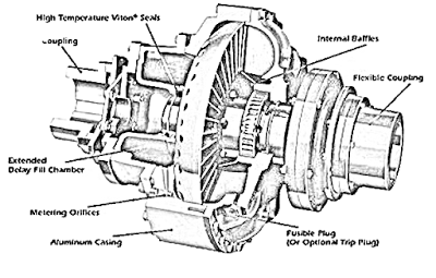
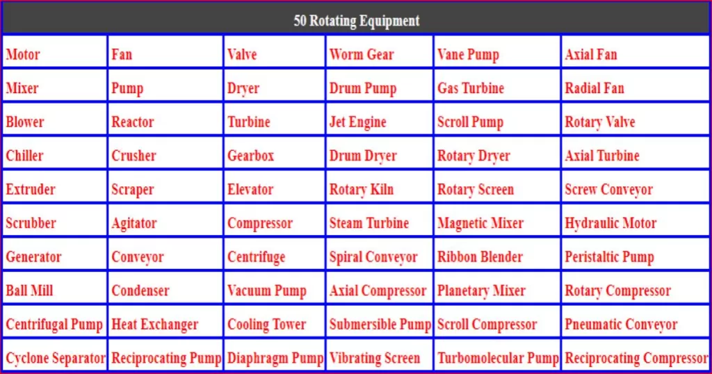
A fluid coupling or hydraulic coupling is a hydrodynamic or hydrokinetic equipment that can transmit power and torque with the help of liquid (hydraulic oil). It belongs to the category of flexible coupling power transmission. This is based on hydrodynamic torque transmission device. It is the assembly of pump impeller, casing gaskets, hydraulic oil, casing, turbine impeller, input shaft, and output shaft. The diagram of this is given below. Nowadays, these couplings are used in many applications, i.e., belt Conveyors, Crushers, Ball and Rod Mills, Agitators and Mixers, Pumps, Fans, Boiler Feed Pumps, gear box, Industrial drives, to provide smooth torque and power transmission. And connect two different equipment shafts to each other for proper operation.
This is an efficient and effective way to transmit power between mechanical elements. By using fluid pressure, couplings regulate the flow of energy so that it is continuously and smoothly distributed among different elements. This guide will explain the principles of fluid coupling operation, compare theoretical evaluations with empirical data, and provide a better understanding of how this types of couplings can benefit your machinery.
The key feature of this coupling is Power Transmission by the help of hydraulic fluid without mechanical connection between driver and driven machine shaft.
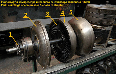
How Does a Fluid Coupling Work?
A fluid coupling works by allowing two components to interact without physical contact. Hydraulic fluid is used to provide a medium of communication. This fluid acts as a cushion, absorbing shock and vibrations between the two units when they start or stop. The components also benefit from improved torque delivery, which allows them to operate more efficiently than connection with a physical drive train. This is typically used in high power applications requiring additional protection, such as those found in military vehicles and other vehicles.
Why fluid couplings Required?
For example, an electric motor is used to rotate a belt conveyor for transporting raw material if the belt conveyor sticks somewhere, and that will produce a shock load on the drive assembly.
There should be a device or system which isolates or disengages to each other and prevents from forming such type of shock load to the motor, but there is not possible by mechanically (physically) connection. Contacted system which can efficiently isolate the driven machine from the drive one like an automobile automatic transmission system when the driver wants to stop the vehicle. He starts applies break the transmission stops its rotation but engine shaft rotation will continue.
That will be possible only by this types of coupling, which allows a controlled amount of slip and mechanically isolate and disengaging the engine from the end point of transmission.
This coupling has the biggest advantages is that power transmission cannot start during the fluid coupling the starting performance of motor, without this coupling the motor instantly transmits its starting torque to the driven machine. It will quickly reach the upper limit and apply the breakdown torque for applications locked rotor and breakdown torque, which often approximates to a hundred percent or more of the motor nameplate rating.
Damage can be a result if the required starting torque of the driven machine is significantly less. The machine will be abruptly accelerated to rated speed with a fluid coupling installed. The torque to the driven machine starts at 0 and gradually increases as the coupling impeller accelerates when the output torque of the fluid coupling exceeds the breakaway starting torque of the driven machine. The Driven Machinery gradually accelerates too.
As the machine comes up to rated speed, the slip of the fluid coupling decreases and uniform power is transmitted reached at maximum efficiency. The motor actually starts in a no-load condition. So, the motor draws less current as compared to other couplings.
Working principle of fluid coupling
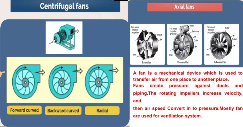
An example beautifully explained the working principle of fluid coupling, a table fan is operating with an electric current which makes the air flow directly hit the other fan blades in front of the first one. Further, other fan blades also state rotating.
Electric motor the impeller motion imparts, both outwards linear rotational motion, high pressure and velocity that impact on the blades of the runner and makes the runner run at the same rotational direction as the impeller during this process. Same principle applies on close casing of fluid coupling.
For fluid coupling when the electric motor starts rotating the coupling impeller, then mechanical energy of the prime mover converts into the kinetic energy and potential energy of hydraulic oil, and then the runner changes that energies of oil into mechanical energy of the output shaft.
What is the torque converter?
Torque converter
As we called a torque converter in that system, the pump typically connected to the flywheel of the engine crankshaft. The turbine is connected to the input shaft of the transmission. The introduction of a stator in between the pump and turbine makes it a little different from the industrial grade fluid coupling. As engine speed increases torque is transferred from the engine to the input shaft by the motion of the fluid propelling the vehicle, but the efficiency is never reached at 100%. In this regard a clutch is used which locks the impeller and turbine at high speed. The behavior of the fluid coupling becomes that of a mechanical clutch driving a manual transmission.
Types of fluid coupling
There are two types of fluid coupling used to connect two different equipment shafts, depending on application, their name and description as below.
- Fixed speed or constant fill type fluid coupling
- Variable speed or scoop type fluid coupling
Fixed speed or constant fill fluid coupling
Fixed fluid couplings constant filling fluid where the oil filling is fixed. In close casings are used to contain oil and other assembly parts. Its operation speed and torque to be provided is fixed. A plug is used for safety purposes. If operating torque goes beyond its upper limits, oil temperature will go up, and used plug melt, through which hydraulic oil drains, then the output shaft stops rotating.
Variable speed or scoop fluid coupling
The scoop coupling provides less speed variation in a wide range when connected with a fixed speed driver. The speed variation got only by the help of varying the oil filling rate through the sliding type scoop tube during operation. Variable filling fluid coupling also known as variable speed fluid coupling where the quantity of oil in the working circuit can be varied whilst running to give control over the amount of slip between the impeller and runner that will give speed regulation. The variable filling fluid coupling also gives a clutching a machine from its drive. It is used extensively in conveyor. for drives to control appropriately the torque applied to equipment during acceleration, and control easily load balancing using external controls.
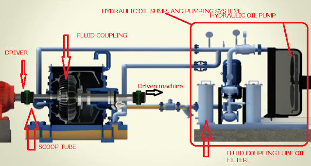
Parts of fluid coupling
There are many parts used to construct the fluid coupling, the name is given below, find from the below list.
Fusible plug, snap ring, washer, impeller, coupling hydraulic seals, bearing, baffle plate, shaft runner, runner, casing chamber, Heli coil and another name as per manufacturer.
Construction of fluid coupling
In the construction of this fluid coupling the pump impeller is closely coupled with the turbine impeller within the coupling casing that only transmits the torque to the output shaft. which is Co Axial with driver shaft as shown in figure.
Preventive maintenance check point
Following points need to be checked during planned preventive maintenance for fluid coupling.
- Check oil quantity and quality of oil
- Checking alignment between both equipment shafts
- Check the seal leakage or failure
- Check parts and plug condition.
- Physical coupling condition
How to check hydraulic oil in the fluid coupling.
First rotate the driver shaft until oil just starts to come out from the oil filling point. Measure the hydraulic oil inside, if found an excess extract from it, and the oil level has gone down, top up the oil in fluid coupling. Then after tighten the cap or replace accordingly if found damaged. But for safety purposes, the plug use in coupling is fusible, for industrial application, the set temperature to melt the plug is approx. 140 degrees Celsius. After melting the plug it will allow the oil to drain.
What types of oil use in fluid coupling?
The fluid is used in fluid coupling, which will directly impact on performance and torque transmission. Usually, hydraulic oil is used in this type of coupling and it is equipped with a self-cooling system to remove the heat, generated by the mechanical part. The selection of fluid and quantity of fluid (Lube oil) has to be filled into fluid coupling depends upon the following factors: motor power, torque to be transferred, coupling slip and motor current. For normal operating conditions, mostly ISO VG 22/ 36 is used. The thumb rule is to fill up hydraulic oil approx. 80% of total capacity of coupling. The level of should be maintained below the overflow, but if cause of over level may be causes increase in oil pressure and the result will be seal failure.
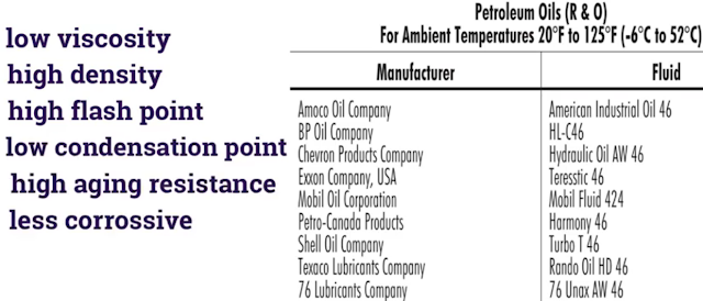
Properties of fluid coupling hydraulic oil
The working oil must be advantaged in low viscosity, high density, high flash point, low condensation point, high aging resistance, less corrosive and good flow ability.
What are advantages of fluid coupling?
- Motor could be starting with no overload, and smooth acceleration of the load
- Driver machine, driven machine and coupling protection during overload and limited to the maximum torque transmitted.
- Motor Selection through the operating torque, and low motor power consumption.
- High efficiency because of the low sliding features
- It can transmit maximum torque capacity, which can be achieved between 80 up to 270% of the operating torque.
- Available with a variety of designs and features.
- If the shaft jams, it will impact increasing stresses on components too many times their normal running values. This coupling slip characteristics spread the absorption of the impact over after some time, reducing stress on the components and therefore protecting rotating equipment. If a jam occurs without a fluid coupling, the motor will start and draw over five hundred percent of full load current. So, it not only can effectively prevent the machine from being broken but also can considerably prolong.
There are some key data to select appropriate fluid coupling for your services. Power Range describes as below Fixed speed for up to 1850 KW, for Variable speed approx. up to 11000 KW. Speed Range for Fixed speed- 720 RPM–3600 RPM, and Variable speed 490 RPM—3600 RPM, Starting torque range for Fixed speed: 80%—280%.
Disadvantage of fluid coupling?
- The two rotors spin at the same angular velocity, there will be no torque developed as no power can be transmitted this way.
- That devices use a liquid or gas as the medium for transferring energy from one component to another.
- When the two components are rotating, the fluid provides a non-slip connection between them, so that energy is efficiently transmitted with minimum loss due to friction.
- However, if either component stops working for any reason, then stalling can occur and cause heat buildup in the coupling, leading to potential damage.
The Benefits of Using a Fluid Coupling
Using this coupling brings many advantages over traditional physical drives. Firstly, fluid couplings protect components from shock loads and excessive vibrations, which can cause long-term damage. The smooth transition of energy delivery also results in better fuel efficiency, as well as improved torque control, which allows faster acceleration and more precise torque output to suit the application. In addition, this couplings is compact in size and generally require minimal maintenance due to their durability.
Maintenance and Troubleshooting Tips for Fluid Couplings
Proper maintenance and troubleshooting are essential for fluid couplings to remain reliable. For starters, you must ensure that enough fluid is added at regular intervals to guard against overheating and excessive wear on the housing. To prevent leaks and minimize energy losses, maintain tight connections between both ends of the coupling at all times. It’s also important to listen out for any strange sounds or vibrations coming from the coupling while in use as they can be a sign of a problem.
Finally, watch out for signs of corrosion or wear on the housing or internal parts, which could indicate a need for more frequent upkeep.
Difference Between Torque Converter and Fluid Coupling
Fluid couplings are somewhat similar to torque converters in that they both involve liquids to transmit rotational energy. However, there are some key differences between them.
First, the main components of a fluid coupling are an impeller and runner, while torque converters have pumps, stators and turbines.
Second, fluid couplings serve solely as a way to connect driving and driven members like an automatic clutch does, but it is not assisted by a friction clutch like torque converters typically are.
Thirdly, fluid couplings are more efficient at highway speeds and never lock up, whereas torque converters may have a slight loss of efficiency at highway speeds but can lock up under speed load.
Finally, movement of oil during engagement in fluid couplings stops when centrifugal forces are approximately equal on both members, but with torque converters the flow of oil never stops entirely.
