ASME B16.47 Flange Dimension Chart
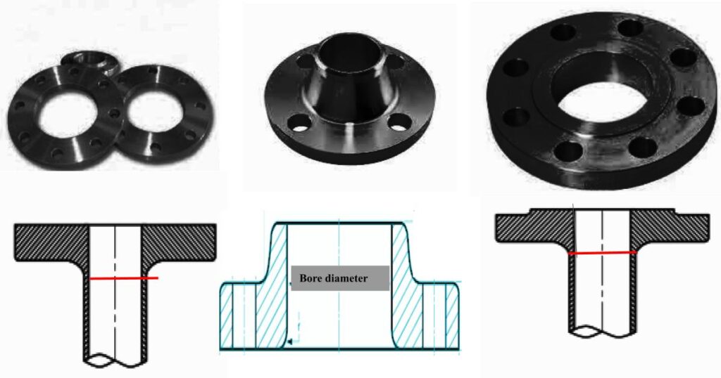
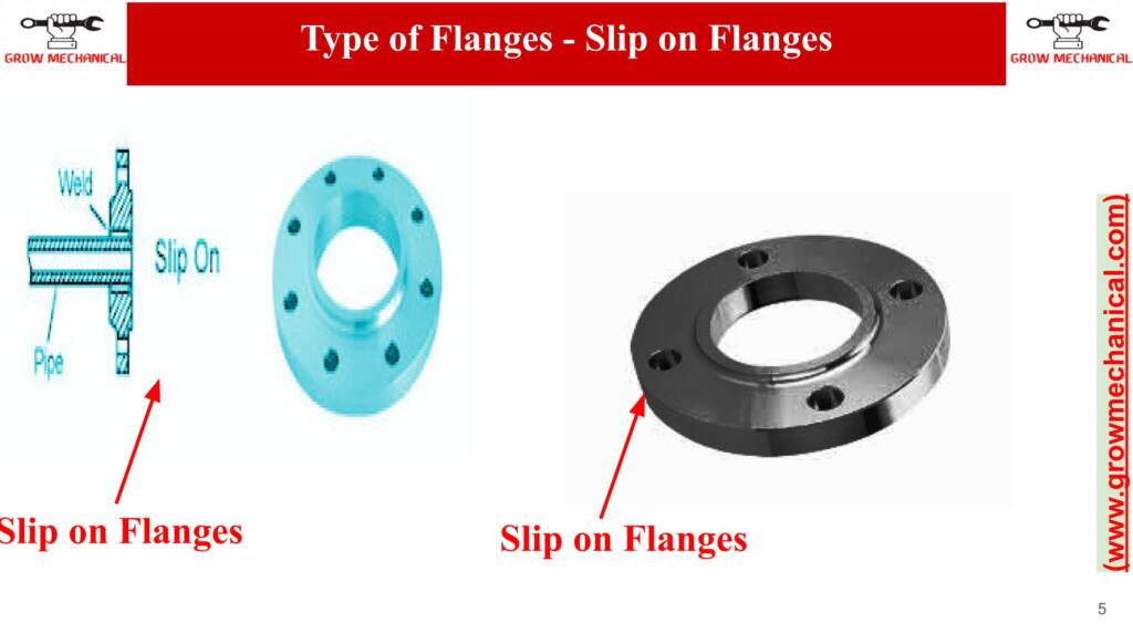
The ASME B16.47 standard provides guidelines for large diameter steel flanges (NPS 26 to NPS 60) used in various industries, including oil and gas, petrochemical, and power generation. The flange dimension chart is a tabular representation that provides essential information to ensure proper flange selection and installation. Here are the key components you can expect to find in the chart:
- Flange Size (Nominal Pipe Size – NPS): The NPS represents the nominal size of the flange and corresponds to the size of the connected pipe.
- Flange Pressure Class: ASME B16.47 flanges are available in various pressure classes, indicating the flange’s pressure rating at specific temperatures and operating conditions.
- Flange Series: The chart may include Series A and Series B flanges, which differ in their pressure ratings and dimensions.
- Facing Type: The facing type refers to the sealing surface of the flange. Common facing types include Raised Face (RF) and Ring Type Joint (RTJ).
- Flange Outer Diameter (OD): The outer diameter represents the overall size of the flange, including the raised face, if applicable.
- Flange Thickness (T): The flange thickness denotes the measurement from the flange’s outer face to its mating surface.
- Hub Diameter (HD): For flanges with a hub, the hub diameter represents the size of the hub.
- Hub Length (HL): The hub length indicates the distance from the flange’s face to the end of the hub.
- Bolt Circle Diameter (BCD): The bolt circle diameter signifies the diameter of the circle formed by the centers of the bolt holes.
- Number of Bolt Holes: The chart provides the number of bolt holes present in the flange.
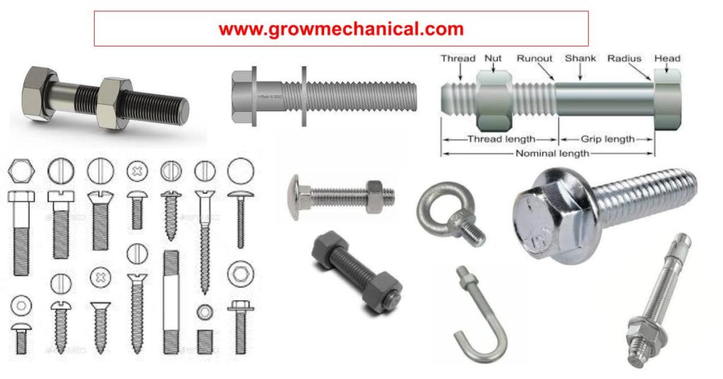
- Bolt Hole Diameter: The bolt hole diameter refers to the size of the holes used for bolting the flange to another component.
- Flange Weight: In some charts, the weight of the flange may be provided for reference.
- Dimensions of Class 150 Series A Flanges
- Dimensions of Class 300 Series A Flanges
- Dimensions of Class 400 Series A Flanges
- Dimensions of Class 600 Series A Flanges
- Dimensions of Class 900 Series A Flanges
Types of ASME B16.47 Flanges
ASME B16.47 flanges come in two main types:
- Series A Flanges: These flanges have smaller and lighter designs, making them suitable for lower pressure and temperature applications. They are commonly used in industries where high-pressure requirements are not a primary concern.
- Series B Flanges: Series B flanges are designed to handle higher pressure and temperature conditions compared to Series A. They are ideal for applications that demand robust and durable flanges capable of withstanding more extreme operating conditions.
ASME B16.47 Flange Dimension Chart Explained
The ASME B16.47 flange dimension chart provides essential information for selecting large-diameter steel flanges (NPS 26 to NPS 60). It includes flange sizes, pressure classes, facing types, outer diameter, thickness, bolt circle diameter, and more. The chart helps ensure proper flange selection, installation, and compatibility with piping systems.
Understanding Flange Sizes and Pressure Ratings
Flange Sizes and Pressure Ratings:
Flange sizes in ASME B16.47 standard are indicated by the Nominal Pipe Size (NPS), which corresponds to the size of the connected pipe. The standard covers large diameter flanges ranging from NPS 26 to NPS 60.
Pressure ratings refer to the maximum allowable pressure a flange can withstand at specific temperatures and operating conditions. Flanges are available in various pressure classes, and higher pressure classes are designed to handle more demanding applications.
Selecting the correct flange size and pressure rating is crucial for ensuring the safety and efficiency of the piping system. Consider the system’s operating conditions and the required pressure capacity when choosing the appropriate flange for your application. Always adhere to the guidelines specified in the ASME B16.47 standard to ensure compliance and reliability.
Facing Configurations in ASME B16.47 Flanges
In ASME B16.47 flanges, two primary facing configurations are commonly used:
- Raised Face (RF): The Raised Face facing type features a raised surface around the flange bore. When two RF flanges are bolted together, the raised faces come into contact, creating a seal. This facing configuration is suitable for low to medium pressure applications and is easy to align during installation.
- Ring Type Joint (RTJ): The Ring Type Joint facing utilizes a metal ring gasket placed within a groove on the flange face. When the flanges are bolted together, the ring gasket is compressed, providing a robust and reliable seal. RTJ flanges are ideal for high-pressure and high-temperature applications, such as those found in the oil and gas industries. Proper alignment during installation is crucial to ensuring an effective seal.
ASME B16.47 Series A vs. Series B Flanges
a tabular comparison of ASME B16.47 Series A and Series B flanges. Please note that the information provided here is a summary, and for detailed specifications, always refer to the latest edition of the ASME B16.47 standard or consult the manufacturer/supplier.
Here’s a tabular comparison:
| Feature | ASME B16.47 Series A Flanges | ASME B16.47 Series B Flanges |
|---|---|---|
| Pressure Rating | Class 75, Class 150, Class 300, Class 400, Class 600 | Class 75, Class 150, Class 300, Class 400, Class 600, Class 900, Class 1500, Class 2500 |
| Flange Size (NPS) | NPS 26 to NPS 60 | NPS 26 to NPS 60 |
| Facing Type | Raised Face (RF), Ring Type Joint (RTJ) | Raised Face (RF), Ring Type Joint (RTJ) |
| Dimensions | Generally larger and heavier | Generally smaller and lighter |
| Applications | General-purpose and lower-pressure applications | High-pressure and critical applications |
| Flange Facings | MSS SP-44 (Raised Face) and API 605 (Ring Joint) | MSS SP-44 (Raised Face) and API 605 (Ring Joint) |
| Gasket Compatibility | Suitable for non-metallic gaskets | Suitable for both metallic and non-metallic gaskets |
| Market Availability | Widespread availability | Less common, usually for specific high-pressure applications |
Please keep in mind that this table serves as a general comparison, and specific details might vary based on the flange’s size, pressure class, and facing type.
Tips for Flange Selection and Installation
Tips for Flange Selection and Installation:
- Properly Determine Requirements: Consider factors such as pressure, temperature, fluid type, and pipe size to select the appropriate flange material, size, and pressure class.
- Know Facing Types: Understand the differences between Raised Face (RF) and Ring Type Joint (RTJ) facing configurations and choose the suitable one for your application.
- Verify Standards: Ensure the flanges comply with ASME B16.47 or other relevant standards to guarantee quality and compatibility.
- Bolt Hole Alignment: Ensure precise alignment of bolt holes during installation to prevent flange distortion and leaks.
- Use Proper Gaskets: Select appropriate gasket materials based on the fluid type and operating conditions to ensure a reliable seal.
- Torque Bolts Correctly: Follow the recommended bolt tightening torque values to achieve the right bolt load and avoid bolt or gasket damage.
- Inspect Flanges: Conduct thorough inspections for defects, damage, or corrosion on flanges before installation to prevent potential issues.
- Lubrication: Apply suitable lubricant on bolts and flange surfaces to ease installation and minimize friction-related problems.
- Flange Protection: Protect flange faces with covers or caps during transportation and storage to avoid damage and contamination.
- Seek Professional Assistance: If unsure, consult with experienced engineers or experts for proper flange selection and installation guidance.
Ensuring Compliance with ASME B16.47 Standards
Ensuring compliance with ASME B16.47 standards is crucial to maintaining the safety, integrity, and efficiency of large diameter steel flanges in industrial applications. To achieve compliance:
- Adhere to Standard Specifications: Follow the exact guidelines specified in ASME B16.47, including flange dimensions, pressure ratings, facing types, and materials.
- Select Approved Materials: Use materials that meet ASME-approved specifications to ensure flange durability and performance.
- Perform Quality Control: Conduct rigorous quality checks during manufacturing to ensure flanges meet required tolerances and standards.
- Implement Proper Installation: Follow recommended installation procedures, including proper torqueing of bolts and gasket placement, to prevent leaks and failures.
- Regular Inspection and Maintenance: Periodically inspect flanges for signs of wear, damage, or corrosion, and perform timely maintenance as needed.
- Conduct Testing: If required, perform hydrostatic or pneumatic testing to verify the flange’s integrity and pressure containment capabilities.
- Stay Updated: Keep abreast of any revisions or updates to ASME B16.47 standards to ensure ongoing compliance.
By adhering to these measures, industries can confidently rely on ASME B16.47-compliant flanges, ensuring a safe and reliable operation of their piping systems.
Troubleshooting Flange Issues
Troubleshooting Flange Issues:
- Leaks: Check for loose bolts, damaged gaskets, or improper installation. Re-tighten bolts following the recommended torque sequence and replace damaged gaskets.
- Gasket Failure: Ensure the gasket material is suitable for the application and operating conditions. Verify proper alignment and even compression during installation.
- Misalignment: Inspect flange alignment and mating surfaces. Use shims or realign the piping system to ensure proper fit.
- Corrosion: Identify the cause of corrosion (e.g., chemical exposure or moisture) and use corrosion-resistant materials or coatings.
- Flange Cracking: Examine for stress concentrations, overloading, or material defects. Use proper reinforcement or replace cracked flanges.
- Bolt Issues: Check for worn or damaged bolts. Replace with suitable grade and size bolts following proper tightening procedures.
- Facing Damage: Inspect for scratches or imperfections on facing surfaces. Repair or replace damaged flanges or facing rings.
- Improper Facing Type: Ensure the correct facing type (RF or RTJ) is used for the specific application and pressure class.
- Temperature Extremes: Verify flange materials can withstand temperature variations. Consider using insulation or heat-resistant materials as needed.
- Flange Material Selection: Confirm flange material compatibility with the fluid being conveyed to avoid material degradation.
- Pressure Surges: Install pressure relief valves or surge protection devices to prevent damage from sudden pressure fluctuations.
- Erosion: Identify erosion-prone areas and implement measures to minimize erosion effects (e.g., flow control, protective linings).
Future of ASME B16.47 Flange Standards
In the future, ASME B16.47 flange standards are expected to evolve with advancements in technology and industry requirements. Innovations may focus on improved materials, more precise manufacturing techniques, and enhanced sealing capabilities. The standards will likely continue to play a vital role in ensuring safe and efficient connections for large-diameter piping systems across diverse applications.


