Understanding Gate valves
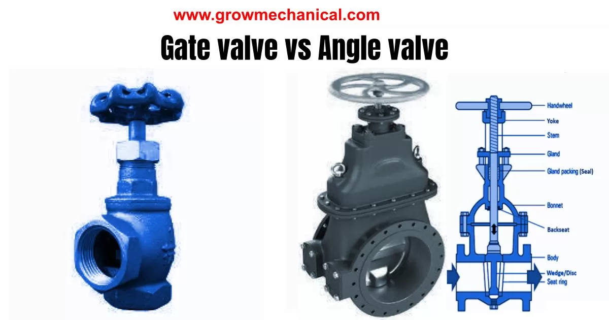
Gate valve is commonly used in industries such as oil and gas, chemical processing, and water treatment. They are used to control the flow of liquids and gases through a pipeline or system. These valves work by using a gate that slides up and down to regulate the flow. It is important to understand how these valves work and their components in order to properly troubleshoot any issues that may arise. The main components of a gate valve include the body, seat, gate, stem, packing, bonnet, hand wheel or actuator.
Gate valves are an essential component of many industrial systems, but they can run into trouble from time to time. Problems with these valves can cause significant disruptions in production and efficiency. Here, we’ll explore some common issues that may arise with GATE valves and offer suggestions for troubleshooting and repairs.
Gate valve failure causes
There are several causes of gate valve failure, including:
- Corrosion: Corrosion is a common cause of valve failure, especially in environments with high levels of moisture or corrosive fluids. Corrosion can cause the valve components to weaken, crack, or fail.
- Wear and Tear: Valves are subject to wear and tear over time, which can cause parts to become misaligned or damaged. This can lead to leaks or reduced performance.
- Improper Installation: Improper installation of the valve can also cause failure. If the valve is not installed correctly, it can cause leaks or other issues that can lead to failure.
- Overuse: Valves that are used frequently can experience wear and tear more quickly, which can lead to failure. This is especially true if the valve is not properly maintained.
- High Pressure: Valves that are exposed to high pressure can also fail if they are not designed to withstand the high pressure.
- Temperature: Extreme temperatures can also cause valve failure, especially if the valve is not designed to withstand the temperature range.
- Manufacturing Defects: Finally, manufacturing defects can also cause valve failure. If the valve is not manufactured to the proper specifications, it may not perform as expected and could fail prematurely.
Proper installation, regular maintenance, and selecting the appropriate valve for the application are all important factors in preventing valve failure.
Trouble shooting for gate valve
Here are some troubleshooting steps for gate valve issues:
- Valve Stuck or Won’t Open/Close: If the valve is stuck or won’t open or close, it may be due to a buildup of debris or corrosion on the valve components. Try cleaning the valve and inspecting it for any damage or wear. If the valve is still stuck, it may need to be replaced.
- Leaks: If the valve is leaking, it may be due to a damaged or worn seal. Try tightening any loose connections and inspecting the valve for any signs of damage. If the seal is damaged, it may need to be replaced.
- Reduced Flow Rate: If the valve is not allowing the desired flow rate, it may be due to a restriction in the valve or a partially closed valve. Check for any obstructions or debris in the valve, and ensure that the valve is fully open.
- Excessive Noise or Vibration: If the valve is producing excessive noise or vibration, it may be due to a loose or damaged component. Inspect the valve for any signs of wear or damage, and tighten any loose connections.
- Failure to Seal: If the valve is not sealing properly, it may be due to a damaged or worn seal. Inspect the seal and replace if necessary.
- Difficulty Turning: If the valve is difficult to turn, it may be due to a damaged or worn stem. Inspect the stem for any signs of wear or damage, and replace if necessary.
If these troubleshooting steps do not resolve the issue, it may be necessary to consult with a valve expert or manufacturer for further assistance.
Gate valve design considerations include:
- Valve Size: The valve size must be carefully considered to ensure that it is appropriate for the flow rate and pressure of the system. This will also affect the size of the gate and other valve components.
- Material Selection: The material used for the valve body, gate, stem, and other components must be carefully chosen to ensure that it is compatible with the fluid being conveyed and the operating conditions of the system.
- Pressure Rating: The valve must be designed to withstand the maximum pressure of the system, with an appropriate safety margin.
- Temperature Range: The valve must be designed to operate within the temperature range of the system, with an appropriate safety margin.
- Stem Sealing: The stem must be designed to provide a secure seal to prevent fluid leakage, and may require a packing gland or other sealing mechanism.
- Gate Position: The position of the gate must be carefully considered to ensure that it provides optimal flow control and is compatible with the system requirements.
- Actuation: The valve may be manually operated or require automated actuation, and the design must take this into consideration.
- End Connections: The valve must be designed with appropriate end connections, such as flanges or threaded connections, to ensure compatibility with the system.
- Maintenance and Repair: The valve must be designed to allow for easy maintenance and repair, with components that can be easily accessed and replaced.
- Standards and Codes: The valve design must comply with relevant industry standards and codes, such as API, ASME, and ISO.
Symptoms of a faulty gate valve
A faulty GATE valve can cause a disruption in the flow of liquids or gases, leading to system failure and downtime. Some common symptoms of a faulty gate valve include leaking around the valve seat, difficulty turning the handwheel or actuator, irregular flow or complete blockage, and unusual noises coming from the valve. If you notice any of these symptoms or performance issues with your valve, it is important to diagnose and repair the issue promptly to prevent further damage to your equipment and system.
Diagnosis and inspection of gate valves
When diagnosing a gate valve, it is important to start with a visual inspection of the valve and its surrounding components. Look for any signs of leakage, corrosion or physical damage to the valve body or stem. Check the actuator or handwheel for damage or wear and observe its operation during use. Consider measuring the pressure drop across the valve to determine if there is any obstruction in the flow path. Additionally, check the condition of packing around the stem of your GATE valve as failures often occur due to improper packing installation or adjustment. Only after a thorough visual inspection can you make an informed diagnosis about what might be causing issues with your GATE valve.
Conclusion
Gate valves are essential components in many industrial applications and can experience various problems, which can affect their performance. The analysis methods for gate valve problems involve visual inspection of the valve components, checking for signs of wear and tear, and ensuring proper lubrication and installation of the valve.
Gate valve root cause analysis by fish bone diagram
A fishbone diagram, also known as an Ishikawa diagram, is a useful tool for analyzing the root causes of a problem. Here’s how a fishbone diagram can be used to analyze the root causes of gate valve problems:
- Start by drawing the fishbone diagram, with the head of the fish representing the problem statement: “Gate valve problem.”
- Draw the major branches or “bones” of the fish, representing the major categories of potential root causes of the problem. Some examples of major categories for gate valve problems include “people,” “process,” “equipment,” “materials,” and “environment.”
- Identify specific subcategories or “bones” for each major category. For example, under the “equipment” category, you might have subcategories like “valve body,” “stem,” “packing,” “gate,” and “seats.”
- Brainstorm potential root causes for each subcategory and write them on the corresponding bone of the fishbone diagram. For example, under the “valve body” subcategory, potential root causes might include “corrosion,” “cracks,” or “debris buildup.”
- Continue this process until you have identified potential root causes for all subcategories of each major category.
- Analyze the fishbone diagram to identify the most likely root causes of the gate valve problem. Look for clusters of related root causes and consider how they might be related to each other. For example, if several subcategories under the “equipment” category have potential root causes related to corrosion or wear and tear, this might suggest that equipment maintenance is a major contributing factor to the gate valve problem.
- Once you have identified the most likely root causes, develop a plan of action to address each one. This might involve implementing a maintenance schedule for gate valves, using higher-quality materials in valve construction, or providing training to personnel on proper valve operation and maintenance.
Using a fishbone diagram to analyze gate valve problems can help identify the root causes of the problem and develop effective solutions to prevent future issues.

