Gate valve definition and introduction
Gate valve is a type of linear motion valve that uses a gate or wedge-shaped disc to control the flow of fluid through a pipeline. When the gate is fully open, it allows the fluid to flow freely through the valve, and when it is fully closed, it completely blocks the flow. Gate valves are designed to control the flow of fluid or gas by using a sliding plate or gate that moves up and down to either allow or block the flow.
Here is some information on gate valves, including its uses, types, applications, operation, working principle, selection guide with calculation and formula, and comparison with other types of valves. In this comprehensive guide, we’ll go over everything you need to know about choosing and applying a gate valve for your project.
Purpose of a Gate Valve
Gate valves play an important role in controlling the flow of fluid or gas within a system. They are commonly used in industries such as oil and gas, water treatment, and power plants. The purpose of a gate valve is to provide full fluid flow when they are open and complete shut-off when they are closed.
Uses of Gate Valve
These are commonly used in applications that require full flow with minimum pressure drop, such as in pipelines that carry water, steam, oil, or gas. They are also used in applications that require tight shutoff, such as in isolation valves or emergency shutdown systems. Gate valves are typically used in industrial applications, including the oil and gas industry, petrochemical industry, power generation, and water treatment plants.
Applications Gate valves
That are suitable for a wide range of applications, including:
- Isolation valves: Gate valves are commonly used as isolation valves to shut off the flow of fluid in a pipeline.
- Emergency shutdown systems: Gate valves are often used in emergency shutdown systems to quickly shut down the flow of fluid in the event of a safety hazard.
- High-pressure applications: Gate valves can withstand high pressure and are often used in high-pressure applications.
- Low-temperature applications: Gate valves can operate at low temperatures and are often used in cryogenic applications.
Operation gate valves
That are operated by raising or lowering a gate or wedge-shaped disc inside the valve body. The gate is attached to a stem, which is connected to an actuator such as a hand wheel, gearbox, or motor. When the actuator is turned, the stem moves up or down, raising or lowering the gate and controlling the flow of fluid through the valve.
Types of gate valves
There are two main types of this valve
- Rising stem gate valves
- Non-rising stem gate valves.
In rising stem gate valves, the stem that connects the gate to the actuator rises as the valve is opened, providing a visual indication of the valve’s position. In non-rising stem gate valves, the stem does not rise, but instead, the gate moves up and down inside the valve body. Other types of gate valves include slab gate valves, expanding gate valves, and split wedge gate valves.
Working principle gate valves
Gate valves work by using a gate or wedge-shaped disc to control the flow of fluid through a pipeline. The gate is moved up or down by a stem that is connected to an actuator, such as a handwheel, gearbox, or motor. When the gate is fully open, it allows the fluid to flow freely through the valve, and when it is fully closed, it completely blocks the flow.
Gate valve Selection with calculation and example
When selecting a gate valve, the following factors should be considered:
- Size: The valve size should match the pipe size to ensure optimal flow and prevent excessive pressure drop.
- Pressure rating: The valve’s pressure rating should match the system’s operating pressure to prevent leaks and ensure safety.
- Temperature rating: The valve’s temperature rating should match the system’s operating temperature to prevent damage to the valve and ensure safety.
- Material: The valve material should be compatible with the fluid being transported to prevent corrosion and ensure longevity.
- End connections: The valve’s end connections should match the pipe’s end connections to ensure proper installation.
To calculate the required valve size, the following formula can be used:
Q = Cv * sqrt (DP/SG)
Where Q = flow rate in gallons per minute (gpm)
Cv = valve flow coefficient
DP = pressure drop across the valve in pounds per square inch (psi)
SG = specific gravity of the fluid
Example: If a gate valve is required for a water pipeline with a flow rate of 1000 gpm, a pressure drop of 10 psi, and a specific gravity of 1.0, and the valve has a Cv of 200, the required valve size can be calculated as follows:
Q = 1000 gpm
Cv = 200
DP = 10 psi
SG = 1.0
Q = Cv * sqrt (DP/SG)
1000 = 200 * sqrt (10/1.0)
1000 = 200 * 3.162
Valve size = 15 inches
Gate valve merits and demerits
Gate valves have several merits and demerits, which are discussed below:
Merits of Gate Valves:
- Full flow: Gate valves offer full unobstructed flow, which makes them ideal for applications that require high flow rates and minimal pressure drop.
- Tight shutoff: Gate valves provide a tight shutoff, which prevents any leakage of the fluid being transported, making them ideal for isolation applications.
- Durability: Gate valves are durable and can withstand high temperatures and pressures, making them suitable for industrial applications.
- Easy to operate: Gate valves have a simple design, and they are easy to operate, making them suitable for applications where quick shut off is required.
- Low maintenance: Gate valves require minimal maintenance and can last for many years without needing to be replaced.
Demerits of Gate Valves:
- Slow operation: Gate valves can be slow to operate, especially if the valve is large or if it has been unused for a long time.
- Limited control: Gate valves are not designed for precise control, and they are limited to on/off applications.
- Pressure drop: Although gate valves offer full flow, they can cause a significant pressure drop, especially if the valve is partially open.
- Fluid compatibility: Gate valves may not be suitable for use with some fluids due to their design, and the material used in construction must be compatible with the fluid being transported.
- Size limitations: Gate valves may not be suitable for use in pipelines with small diameters, as the valve size may be too large.
In summary, gate valves have several advantages, such as full flow, tight shutoff, durability, easy operation, and low maintenance. However, they also have some disadvantages, such as slow operation, limited control, pressure drop, fluid compatibility, and size limitations. The selection of a gate valve for a particular application should take these factors into account.
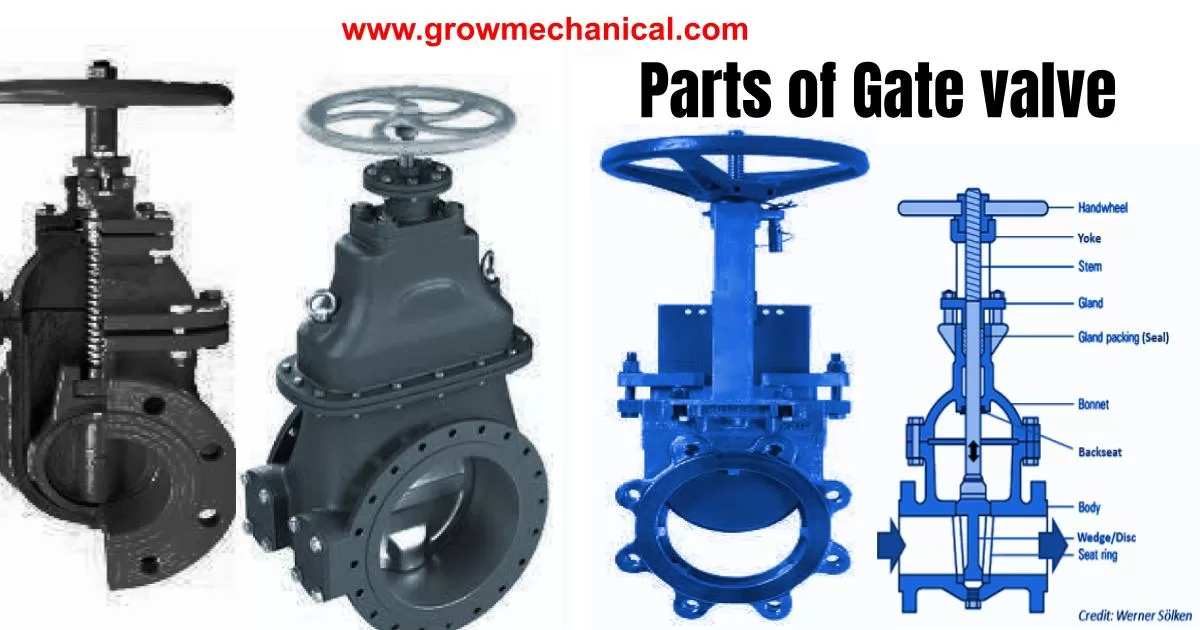
Parts of gate valve and it uses
The following is a list of the main parts of a typical gate valve:
- Body: The main part of the valve that contains the flow path.
- Bonnet: The top part of the valve that covers the stem and packing.
- Stem: The valve component that connects the handwheel or actuator to the gate, allowing it to open or close.
- Gate: The valve component that moves up and down to control the flow of the fluid.
- Wedge: The gate may have a wedge-shaped design to provide a tight seal when the valve is closed.
- Seat: The part of the valve that provides a sealing surface against which the gate or wedge rests when the valve is closed.
- Packing: A material such as graphite or PTFE that is used to seal the space between the stem and the bonnet to prevent leaks.
- Gland: The part of the valve that compresses the packing around the stem to prevent leaks.
- Handwheel: A manual device used to operate the valve by turning it clockwise or counterclockwise.
- Yoke: A structural support that connects the bonnet to the valve body.
- Stem nut: A threaded component that moves up and down the stem, allowing it to open or close the valve.
- Stem guide: A component that guides the stem, keeping it aligned with the gate.
- Backseat: A feature that allows the stem to be extended without exposing the packing to the fluid flow.
- Bolts and nuts: These are used to connect the valve body to the pipeline.
- Flanges: The end connections of the valve that are used to connect it to the pipeline.
This list may not be exhaustive, and the actual design of a gate valve may vary depending on its application and manufacturer.
Standards and code for gate valve
There are several standards and codes that govern the design, materials, and other requirements for gate valves. Here are some of the most commonly used standards:
- ASME B16.34: This standard covers the requirements for gate, globe, and check valves in various materials, sizes, and pressure classes.
- API 600: This standard covers the design, materials, and testing requirements for steel gate valves for the petroleum and natural gas industries.
- API 602: This standard covers the design, materials, and testing requirements for forged steel gate, globe, and check valves for small-diameter, high-pressure applications.
- MSS SP-44: This standard covers steel pipeline flanges for sizes NPS 26 through NPS 60.
- ASTM A216/A216M: This specification covers carbon steel castings for valves, flanges, fittings, and other pressure-containing parts for high-temperature service.
- ASTM A351/A351M: This specification covers austenitic steel castings for valves, flanges, fittings, and other pressure-containing parts.
- ASTM A352/A352M: This specification covers steel castings for valves, flanges, fittings, and other pressure-containing parts for low-temperature service.
- ASTM A105/A105M: This specification covers forged carbon steel piping components for ambient- and higher-temperature service.
- ASTM A182/A182M: This specification covers forged or rolled alloy and stainless steel pipe flanges, forged fittings, and valves for high-temperature service.
- ISO 10434: This standard covers the requirements for steel gate, globe, and check valves for the petroleum, petrochemical, and natural gas industries.
- ISO 14313: This standard covers the requirements for pipeline valves used in the petroleum and natural gas industries.
In addition to these standards, there may be other codes and regulations that apply to specific applications or industries, such as the American Water Works Association (AWWA) standards for water and wastewater applications, or the European Pressure Equipment Directive (PED) for pressure equipment in Europe.
Determine Your Project Needs
Before selecting a gate valve for your project, it’s important to determine your specific needs. Consider factors such as the type of fluid or gas being transported, the pressure and temperature requirements, and the size and capacity of the system. It’s also important to consider any environmental or safety regulations that may impact your decision. By carefully evaluating your project needs, you can ensure that you select a gate valve that will provide reliable and efficient operation.
Consider Valve Material and Size
When selecting a gate valve, it’s important to consider the material and size of the valve. The material should be appropriate for the type of fluid or gas being transported and the conditions under which it will operate. For example, if the valve will be exposed to corrosive environments, a corrosion-resistant material such as stainless steel may be required. Size is also an important factor in selecting a gate valve. It’s essential that you choose a valve that is compatible with your system’s pipes to ensure efficient operation. Ensure that you carefully evaluate these factors before making your purchase decision.
Choose the Right Type of Gate Valve
Gate valves are divided into three main categories: full port, reduced port, and v-port. Full port gate valves have a larger passage size, which ensures minimal pressure drop and allows the unobstructed flow of fluids. Reduced port gate valves have a smaller passageway size than full port valves, resulting in greater flow resistance and pressure drop. V-port gate valves have a V-shaped bore and a specially designed seat that allows for precise control of fluid flow. When selecting a gate valve, it’s important to choose the type that best fits your specific application needs.
Difference between full bore half, one piece, two piece, three piece gate valve
Full Bore vs. Reduced Bore:
A full bore gate valve has a bore diameter that is the same as the pipeline diameter, which means that the valve provides minimal flow restriction when fully open. In contrast, a reduced bore gate valve has a bore diameter that is smaller than the pipeline diameter, which can cause flow restrictions and pressure drops. Full bore gate valves are typically used in applications where high flow rates and low pressure drops are required.
One-piece, Two-piece, and Three-piece Gate Valves:
Gate valves can be classified based on their construction into one-piece, two-piece, or three-piece designs. One-piece gate valves have a single body that contains the valve components, while two-piece and three-piece gate valves have bodies that are made up of two or three separate pieces.
One-piece gate valves are generally the simplest and most economical design, but they may be more difficult to repair or replace if any components become damaged. Two-piece and three-piece gate valves are easier to disassemble and repair, as they can be taken apart without removing the entire valve from the pipeline.
Trim materials for gate valve
The trim of a gate valve refers to the internal components of the valve, including the gate, seat, stem, and packing. These components are typically made of different materials depending on the specific application and service conditions.
The gate and seat of a gate valve are usually made of materials that are resistant to wear, corrosion, and erosion. Common materials for gate and seat include stainless steel, carbon steel, and bronze.
The stem and packing of a gate valve are often made of materials that are resistant to chemical attack and high temperatures. Common materials for the stem and packing include graphite, Teflon, and various polymers.
The selection of trim materials for a gate valve is critical to ensuring that the valve performs reliably and has a long service life. It is important to choose the appropriate materials based on the specific service conditions, such as fluid type, pressure, temperature, and flow rate.
Gate valve selection criteria
The selection criteria for gate valves may vary depending on the specific application, but some common considerations include:
- Size: The valve size should be appropriate for the flow rate and pressure of the system.
- Operating Pressure: The valve should be designed to withstand the maximum pressure of the system, with an appropriate safety margin.
- Temperature Range: The valve should be designed to operate within the temperature range of the system, with an appropriate safety margin.
- Fluid Compatibility: The material used for the valve body, gate, stem, and other components should be compatible with the fluid being conveyed and the operating conditions of the system.
- Valve Type: There are various types of gate valves, such as full port or reduced port, that can affect the flow rate and pressure drop of the system. The valve type should be selected based on the specific application requirements.
- End Connections: The valve should have appropriate end connections, such as flanges or threaded connections, to ensure compatibility with the system.
- Actuation: The valve may require manual or automated actuation, which should be considered based on the specific application requirements.
- Standards and Codes: The valve should comply with relevant industry standards and codes, such as API, ASME, and ISO.
- Maintenance and Repair: The valve should be designed to allow for easy maintenance and repair, with components that can be easily accessed and replaced.
- Cost: The cost of the valve should be considered based on the specific application requirements and budget.

