Pipeline Inspection and testing
Inspection plays an important role to ensure Sustainability, Reliability, Safety and integrity for Plant and Industries pipelines. That is used to ensure the Sustainability, Reliability, Safety and Integrity of the system, and ensure that system integrity will not be compromised so it needs to be designed with care and follow all recommended standards and codes.
There are some important types of testing and inspection mentioned below for piping systems. Most of are generally performed on raw material, equipment, fittings or parts, and some of after fabrication, installation and commissioning and existing systems periodically.
The inspection, examination, and testing of piping systems is covered in Chapter VI of B31.3, and Chapter VI covers the following subjects:
Why Inspect?
- To identify deterioration mechanisms
- To specify repair, replacement, future inspections.
- Reliability and Efficient Operation Regulatory requirements
- Safety
The ASME B31.3 standard specification is divided into examination and inspection. In which examination applicable for quality control and activity will be fulfilled by the manufacturer of piping components for the fabrication or erection. Inspection will be done by a piping inspector who should be aware about his roles, responsibility and standard procedure for testing the work piece. For example
- What should he know?
- Where should he inspect?
- What should he inspect?
- How should he inspect?
- When should he inspect?
Types of Examination
There is a list of examination and test performing for ensure the integrity, quality and reliability of pipe, fittings and pipeline. These are as below.
- Visual Examination.
- Ultrasonic Examination
- Pressure Testing Systems
- Radiographic Examination.
- Liquid Penetrant Examination
- Magnetic Particle Examination.
- Special Provisions for Testing
- Proof Tests
- Holiday testing .
- Piping Weld Hardness Tests .
- Initial Service Leak Testing
- Hydrostatic and Pneumatic Testing
- Combination Hydrostatic-Pneumatic Leak Test
- Important Code and standard of testing and inspection for equipment, piping/pipeline and plants.
Piping Weld Hardness Tests
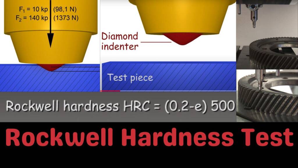
Hardness test is a type of Non Destructive test required for inspecting the welds joints according to standards like the ISO 9015 and the ISO 15614 Specification. Hardness testing shall be carried out after welding procedure qualification on cross sectional. Nowadays hardness testing shall be carried out by portable digital hardness testers. Poldi hardness testers shall not be permitted. Contractor shall produce documentary evidence/calibration certificate to the Inspector and take approval of the hardness testing equipment.
Piping Weld Hardness Test Procedure
A hardness test is generally performed by pressing a fixed dimensioned weighted object (called indenter) into the surface of the workpiece which you are testing. The hardness is achieved by measuring the depth of indenter penetration or by measuring the size of the impression left by a press weighted object (indenter). The three most commonly used test methods nowadays are the Brinell test, the Vicker’s Diamond test, and the Rockwell test.
Holiday testing
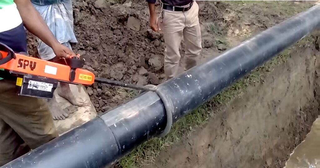
Holiday testing is a type of non-destructive test method which is applied on protective coatings (rapid coating for underground pipings) to detect layer discontinuities. Because that will affect the integrity of linings such as pinholes and voids. In this test perform by checking an electric circuit to see if there are inappropriate linings, pinholes and voids of coating to resist the electrical charge and current flows to complete the circuit. If electrical flow is detected then it shows the presence of a pinhole, a holiday (discontinuity) or inappropriate coating. This testing is also known as continuity testing and it is very useful for tests and inspection of other types of coating as well like rubber lining tanks, glass lined reactors etc.
|
 |
In this test a holiday detector (electrical device) is used to conduct the holiday test as described above. Nowadays there are various methods/technologies and equipment used for holiday detection. It can be performed by flowing low voltage or high voltage current across the chosen path (pipes or equipment). The current selection is depending on the coating thickness. Low-voltage holiday testing is performed when the coating thickness is less than 500 microns (.5 MM) thick. This is generally performed by using the wet sponge method. A high-voltage holiday testing is performed when the applied coating thickens on piping or equipment that is more than 500 microns (.5 MM) thick .
High-voltage holiday
High-voltage holiday testing requires special care to prevent any damage to the coating or save from injury to the workmen / operator. Each industry has its own guidelines on best practices and standards (e.g. ASTM) that need to meet the minimum requirement on lining/coating preparation, inspection and repair. Generally, large applications for holiday testing include finding discontinuities / pinholes in coating of piping and structures, storage tank interiors, and rubberized waterproofing on concrete.
There are some important coating and lining codes and standards (American Society for Testing and Materials) are given as below.
ASTM D5162 – This Standard Practice is generally used for test discontinuity (Holiday) and Nonconductive Protective Coating on Metallic Substrates.
ASTM D4787-13- This Standard Practice uses Continuity Verification of Liquid or Sheet Linings Applied to Concrete materials.
ASTM G62-14 – This is a test method for Holiday Detection in Pipeline Coatings only.
Visual Examination Test
The visual examination is an important part of a piping system and that should be carried out as per the latest editions of the applicable codes and specifications such as in BPV Code, Section V, Article 9 or other.
Basically visual examinations performed with the naked eye for weld joint, alignment, reinforcement, concavity and cracks of welds, inadequate penetration, dimensions of weld, surface porosity etc. The visual examination is carried out by the naked eye and the following application defects should be identified and inspected.
- Correct weld preparation.
- Weld penetration
- Surface defects, porosity and cracks.
- Weld profile (cap, root).
- Measurement of component geometry.
- Measurement of surface roughness.
- Detection of corrosion.
- Detection of defects and cracks.
- Detection of excess grinding defects.
Magnetic Particle Examination
Magnetic particle inspection (MPI) testing of weld joints is a very effective type of surface inspection methods that apply in detecting the surface and shallow subsurface discontinuities or inappropriate, or flaws detection in ferromagnetic materials such as iron or steel. This is a non-destructive test method that allows for visual inspections to quickly and efficiently detect any weaknesses in the weld, then be evaluated and rectified. The seven most frequent welding defects are listed and that should be checked during MPI.
- Cracks (these can be hot cracks, cold cracks, and crater cracks),
- Undercuts,
- Porosity,
- Incomplete fusion,
- Slag inclusion,
- Incomplete penetration, and
- Spatter
Radiographic Test
Radiographic testing (RT) is a non-destructive testing method for examining the for weld test piece by the help of X-rays or gamma-rays to produce a radiograph of the workpiece for changes in thickness or detect defects. These X-rays are generated by an X-ray tube and gamma rays are produced by an isotope.
Now day there are a variety of isotope sources and x-ray machines available in different equipment available in different size that is able to inspections within plates area and pipes to detect defects in welds and corrosion as well as blockage including cracks, slag, pores and porosity, inclusions and lack of fusions and other. Like as
- Se75 Isotope for steel 5 to 20mm
- Ir192 Isotope for steel 10 to 50mm
- Co60 Isotope for steel 25 to 200mm
- X-rays for steel various thicknesses
Proof Tests / Burst test
The proof test is a type of test in which the manufacturer has to prove his design that fittings are able to withstand desired pressure. Whereas hydro-tested pipe shall be used to manufacture fittings, and the weld seam is subjected to 100% radiography to ensure the integrity of the weld, and therefore no lake from the weld in future.
To validate the design of the pipe fitting, the manufacturer performed various tests, like burst tests to ensure that the design will meet all the standard & code requirements. Burst tests – In this test, a pipe & fittings are welded and a dummy pipe spool is prepared. Then that pipe spool is pressurized to pre-define calculated burst test pressure and in some cases keep pressurizing the fitting till it does not burst.
Hydrostatic Testing
Hydrostatic testing is the most important and common method used for identifying the leakage in pipe, equipment or piping networks. In process piping code specification ASME B31.3 is explained about general criteria and guidelines for hydro testing in a process industry.
Test Fluid
As per ASME B31.3 Section 345.4.1, the test fluid shall be water or in any special cases can not be performed with water due to the possibility of damage to the pipe or equipment by changes in water properties like freezing or adverse effects. In that scenario another suitable non toxic liquid may be used with proper sop and clint approval. If the used test liquid is flammable than that flash point shall be at least 49°C (120°F) or more, and the test environment will be considered.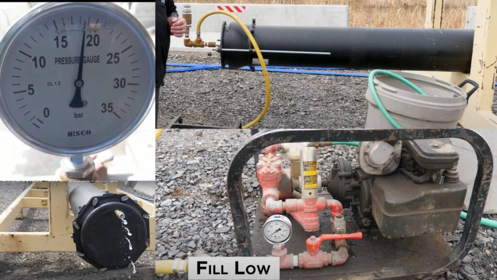
Test Pressure
According to ASME B31.3 Section 345.4.2 the hydrostatic test pressure at any point in a metal piping or equipment system shall be as follows:
- Test pressure should not be less than 11⁄2 times the design pressure.
- For design temperatures above the test temperature,
- The minimum test pressure shall be calculated.
- The value of ST(stress value at test temperature) / S (stress value at design temperature) shall not exceed 6.5.
where
P = internal design gauge pressure, PT = minimum test gauge pressure, S = stress value at design temperature (see Table A-1 of B31.3), ST = stress value at test temperature.
Pneumatic testing
This testing is also very common where hydrostatic testing cannot be done or water can damage the piping or equipment system. It is a decision taken by the client or design/engineering department. This test shall be performed according to ASME B31.3 section 345.5 specification the minimum requirements of pneumatic testing precautions mentioned in article 345.5.1.
Some known hazards always present with pneumatic testing like stored energy (compressed gas / air) can be released and care must be taken to minimize the chance of brittle failure during a pneumatic leak test. Test temperature is important and must be considered during the designing and selection of the construction of materials for more learning. See para. 345.2.2(c) and Appendix F, paras. F323.4 and F345.5.1 and Para 345.5.2 for pressure relief devices like PSV/ PRV and others. The pressure relief device that you have installed sets pressure should not be more than 1.1 times of test pressure or 10% higher than test pressure. Para 345.5.3 describes test fluid or gas used as test fluid, if not air, shall be nonflammable and nontoxic.
Salient Features of Pneumatic Testing
Pneumatic testing pressure is normally 10% higher than the design pressure of a piping system.
Pneumatic testing is recommended only for low pressure applications not for higher pressure .
Generally compressed air is used as test fluid and easy to clean equipment or pipelines after pneumatic testing.
Pressure relief devices are required during the test to ensure or prevent over-pressurization.
Very high chances of equipment/pipe / test apparatus failures.
Easy to carry due to the weight of equipment with test medium as air is less.
Before starting pneumatic testing, it is very essential to carefully check and rectify if any defects are found in weld joints.
The skilled supervisor and workmen required to perform the pneumatic testing.
Standards Dye Penetrant Inspection
Liquid penetrant inspection test is used to detect any surface discontinuities in welds joint and other such as cracks, fatigue failure, porosity, incomplete fusion, and flaws. Here is a list of ISO standards nowadays generally followed in industry related to dye penetrant inspection.
These are all non-destructive types of test methods, ISO 3451 totals divided in 6 parts.
1 – ISO 3452-1 Penetrant testing – Part 1. General principles
2 – ISO 3452-2 Penetrant testing – Part 2: Testing of penetrant materials
3 – ISO 3452-3 Penetrant testing – Part 3: Reference test blocks
4 – ISO 3452-4 Penetrant testing – Part 4: Equipment
5 – ISO 3452-5 Penetrant testing – Part 5: Penetrant testing at temperatures higher than 50
6 – ISO 3452-6 Penetrant testing – Part 6: Penetrant testing at temperatures lower than 10
7 – ISO 3059 Penetrant testing and magnetic particle testing – Viewing conditions
8- ISO 12706 Penetrant testing – Vocabulary
Important Code and standard uses now day for testing and inspection
- API STD 600– Bolted bonnet steel gate valves for petroleum & natural gas industries
- API STD 570- Inspection, repair, Alteration & re rating of in service piping system.
- API STD 598- valve inspection & testing
- API STD 1104- This standard specification explains welding of pipelines & related facilities.
- ASTM – A106 / A53 – for carbon steel seamless piping
- ASTM- A312 – for austenitic SS seamless piping
- ASTM A335 – for low alloy steel seamless piping
- ASTM-A333 – for LTCS piping
- ASTM-A358 – for welded austenitic stainless piping
- ASTM A671/672 – EFW – CS and LAS piping

