What is a Needle Valve and How Does it Work?
Needle valves are essential components used in various industries, including petrochemical, gas, and oil industries. These valves are primarily used for flow control, providing accurate control over the flow rate of liquids or gases through a pipeline. A needle valve is designed with a long, tapered, and pointed needle-like stem that moves through a small orifice, allowing for precise control over the flow of the fluid.
Needle valves come in various sizes, materials, and designs to suit different applications. They are widely used in low-flow applications that require high precision and accuracy, such as fuel injection systems, laboratory equipment, and medical devices.
Types and Applications of Needle valve
There are different types of needle valves available in the market. Some of the most common types of needle valves include:
- Screwed Bonnet Needle Valve: This type of valve is designed with a threaded bonnet and a needle-like stem, making it easy to install and maintain.
- Screwed Bonnet Needle Valves are commonly used in low-pressure applications, such as hydraulic and pneumatic systems.
- Integral Bonnet Needle Valve: Integral Bonnet Needle Valves are designed with a one-piece body and bonnet, providing better structural integrity and resistance to leaks. These valves are commonly used in high-pressure applications, such as chemical and refining industries.
- Union Bonnet Needle Valve: Union Bonnet Needle Valves are designed with a removable bonnet, allowing for easy maintenance and cleaning. .
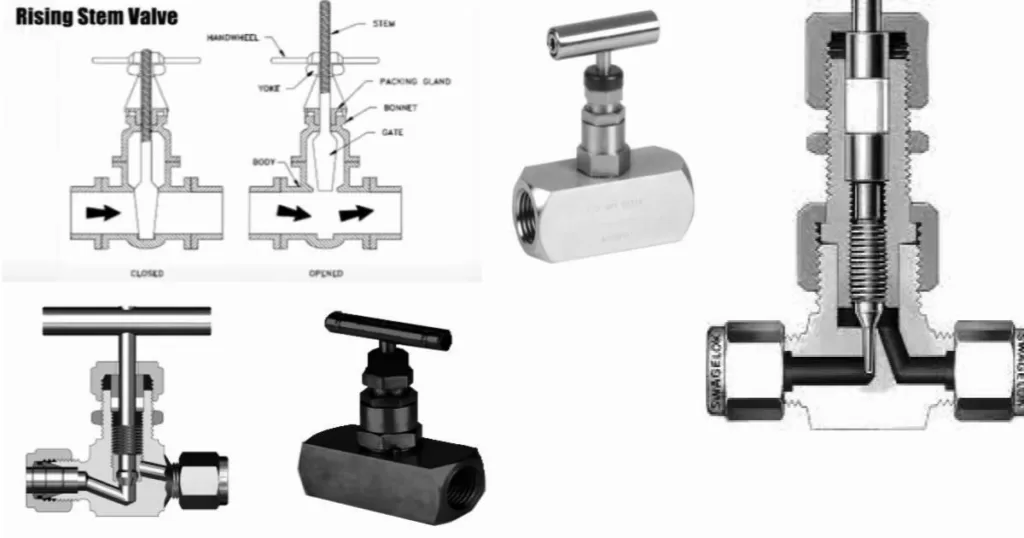
- Rising Stem Needle Valve: Rising Stem Needle Valves are designed with a stem that moves vertically as it is turned, allowing for precise control over the flow rate. These valves are commonly used in applications where accurate control is essential, such as in laboratory equipment and medical devices.
Needle Valve Selection:
Here is a Step-by-Step Guide to Selection and Sizing
Choosing the right needle valve for your application is crucial to ensure optimal performance and efficiency. There are several factors that you should consider when selecting a needle valve, such as the material, pressure rating, temperature range, and flow rate.
Material:
The material of the needle valve should be selected based on the type of fluid and the operating conditions. For example, if you are working with corrosive fluids, you may need a needle valve made of materials such as stainless steel, Hastelloy, or Monel. On the other hand, if you are working with high-temperature fluids, you may need a needle valve made of materials such as Inconel or titanium.
Pressure Rating:
The pressure rating of the needle valve should be selected based on the maximum pressure that the valve will be exposed to during operation. Needle valves are rated for maximum pressure, which can range from a few hundred psi to several thousand psi.
Temperature Range:
The temperature range of the needle valve should be selected based on the maximum and minimum temperatures that the valve will be exposed to during operation. Needle valves are designed to operate within a specific temperature range, which can range from -20°C to 500°C or higher.
Flow Rate:
The flow rate of the needle valve should be selected based on the desired flow rate and the size of the pipeline. Needle valves are available in different sizes, which can range from 1/8″ to 2″ or larger. The flow rate of the valve is directly proportional to the size of the orifice, and it can be calculated using standard equations.
Example of Needle Valve Selection:
Let’s assume that you need a needle valve for a low-pressure hydraulic system that operates at a maximum pressure of 500 psi and a temperature range of -10°C to 60°C. The fluid is non-corrosive, and the desired flow rate is 5 liters per minute.
Based on these specifications, you can select a 1/4″ Screwed Bonnet Needle Valve made of stainless steel, which has a pressure rating of 500 psi and a temperature range of -20°C to 500°C. The orifice size of the valve can be calculated using the standard flow rate equation,
Which is Q = Cv x √(ΔP/SG), where Q is the flow rate, Cv is the valve coefficient, ΔP is the pressure drop across the valve, and SG is the specific gravity of the fluid.
Codes and Standards:
Needle valves are designed and manufactured in accordance with various codes and standards, such as ASME B16.34, API 6D, and ISO 15761. These codes and standards provide guidelines for the design, materials, testing, and inspection of needle valves to ensure their safe and reliable operation. When selecting a needle valve, it is essential to ensure that it complies with the relevant codes and standards to ensure its quality and reliability.
All Part List of Needle Valve and their Uses:
Needle valves consist of several parts, each of which plays a critical role in controlling the flow of fluids. Some of the most common parts of a needle valve include:
Valve Body:
The valve body is the main housing that contains the other components of the valve. It is designed to withstand the pressure and temperature of the fluid flowing through the valve.
Bonnet:
The bonnet is the top part of the valve that provides access to the stem and seat. It is typically threaded onto the valve body and tightened to create a seal.
Stem:
The stem is a long, tapered, and pointed needle-like rod that moves through the orifice to control the flow of the fluid.
Seat:
The seat is a small, circular ring that provides a sealing surface for the stem. It is typically made of materials such as metal, plastic, or ceramic.
Packing:
The packing is a material that surrounds the stem and creates a seal between the stem and the bonnet. It is typically made of materials such as graphite, PTFE, or elastomers.
Handle:
The handle is used to turn the stem and control the flow of the fluid. It is typically made of materials such as metal or plastic.
Nut:
The nut is used to secure the handle onto the stem. It is typically threaded onto the stem and tightened to prevent the handle from coming loose.
Standards and Metrology:
Standards and metrology play a crucial role in ensuring the quality and reliability of needle valves. Standards are guidelines and specifications that define the design, materials, testing, and performance requirements of needle valves. These standards are developed by organizations such as the American Society of Mechanical Engineers (ASME) and the International Organization for Standardization (ISO).
Metrology
Metrology is the science of measurement, and it plays a critical role in ensuring the accuracy and precision of needle valves. Metrology is used to calibrate and verify the performance of instruments and equipment used in the manufacturing and testing of needle valves. Some of the most common standards and metrology methods used in the manufacture and testing of needle valves include:
- ASME B16.34: This standard defines the design, materials, testing, and performance requirements of valve bodies, bonnets, and end connections.
- API 6D: This standard defines the design, materials, testing, and performance requirements of pipeline valves, including needle valves.
- ISO 15761: This standard defines the terminology and testing methods used in the performance evaluation of control valves, including needle valves.
Needle Valve Specific Requirements for Uses:
Needle valves are used in a wide range of applications that require precise control over the flow of fluids. The specific requirements for the use of needle valves depend on the application and the type of fluid being controlled. Some of the most common requirements for the use of needle valves include:
Pressure Rating:
Needle valves must be rated for the maximum pressure of the fluid being controlled. The pressure rating is determined by the material and design of the valve body and components.
Temperature Rating:
Needle valves must also be rated for the maximum temperature of the fluid being controlled. The temperature rating is determined by the material and design of the valve body and components.
Flow Rate:
Needle valves must be selected based on the required flow rate of the fluid being controlled. The flow rate is determined by the size of the valve orifice and the pressure drop across the valve.
Fluid Compatibility:
Needle valves must be made of materials that are compatible with the fluid being controlled. The chemical and physical properties of the fluid can affect the performance and durability of the valve.
End Connections:
Needle valves must be selected based on the type and size of the end connections required for the application.
Operation:
Needle valves must be selected based on the required method of operation, such as manual, electric, or pneumatic.
Needle Valve Size and Types Calculation for Pipeline:
Needle valves are commonly used in pipelines to control the flow of fluids. The size and type of needle valve required for a pipeline depend on various factors, such as the fluid being transported, the pipe diameter, and the pressure drop across the valve. The following formula can be used to calculate the size of the needle valve required for a pipeline:
Q = K * d^2 * sqrt(P1-P2) / Viscosity
- Where: Q = Flow Rate (GPM)
- K = Flow Coefficient (dimensionless)
- d = Orifice Diameter (inches)
- P1 = Inlet Pressure (psig)
- P2 = Outlet Pressure (psig)
- Viscosity = Fluid Viscosity (cP)
The flow coefficient (K) is a measure of the valve’s efficiency and is typically provided by the valve manufacturer. The orifice diameter (d) can be calculated based on the required flow rate and the pressure drop across the valve.
Needle Valve Parts Code and Standards for Selection:
When selecting needle valves for specific applications, it is important to consider the different parts codes and standards that are relevant to their design and manufacturing. Some of the most common codes and standards for needle valves include:
- ASME B16.34: This standard covers the requirements for steel, bronze, alloy, and cast iron threaded and welded end needle valves with a pressure-temperature rating.
- API 598: This standard covers the testing of valve pressure boundary and valve seat integrity.
- MSS SP-99: This standard covers the requirements for instrumentation valves and manifolds.
- ASTM A182: This specification covers forged or rolled alloy and stainless steel pipe flanges, forged fittings, and valves and parts.
- NACE MR0175/ISO 15156: This standard covers the requirements for materials that can be used in environments containing H2S.
- ANSI/FCI 70-2: This standard covers the classification of valve leakage rates.
Leakage Class for all types of Valve:
The leakage class of a valve is a measure of the maximum allowable leakage rate through the valve when it is fully closed. The American National Standards Institute/Fluid Controls Institute (ANSI/FCI) provides a classification system for valve leakage rates, which is defined as:
- Class I: No visible leakage is permitted.
- Class II: Leakage is permitted, but it should not exceed a rate of 0.1% of the valve’s rated capacity.
- Class III: Leakage is permitted, but it should not exceed a rate of 0.5% of the valve’s rated capacity.
- Class IV: Leakage is permitted, but it should not exceed a rate of 1% of the valve’s rated capacity.
- Class V: Leakage is permitted, but it should not exceed a rate of 2% of the valve’s rated capacity.
- Class VI: Leakage is not specified, and it is determined by the valve manufacturer.
In conclusion, understanding the different parts codes and standards that are relevant to needle valves is important when selecting them for specific applications. The leakage class of a valve is also an important consideration, as it is a measure of the maximum allowable leakage rate through the valve when it is fully closed.
Needle Valves: Introduction, Type, Selection and application PDF
Leakage Class for Different Types of Valves:
The leakage class of a valve is a measure of the maximum allowable leakage rate through the valve when it is fully closed. The American National Standards Institute/Fluid Controls Institute (ANSI/FCI) provides a classification system for valve leakage rates, which is defined as:
- Globe valves: Class I, II, III, IV, V, or VI.
- Ball valves: Class IV, V, or VI.
- Gate valves: Class IV or V.
- Butterfly valves: Class IV or V.
- Check valves: Class III or IV.
- Diaphragm valves: Class I, II, III, IV, V, or VI.
Needle Valve Pressure Drop Calculation:
The pressure drop across a needle valve can be calculated using the following formula:
ΔP = K × Q²
Where: ΔP = Pressure drop (psi), K = Pressure drop coefficient (dimensionless), Q = Flow rate (gpm)
The pressure drop coefficient (K) is dependent on the valve’s size, shape, and the properties of the fluid. It can be obtained from the manufacturer’s data or calculated using empirical equations.
The flow rate (Q) can be determined based on the requirements of the system and the valve’s Cv (flow coefficient), which is a measure of the valve’s flow capacity. The Cv can also be obtained from the manufacturer’s data or calculated using the following formula:
Cv = Q / √ΔP
Where: Cv = Flow coefficient (gpm/psi^0.5), Q = Flow rate (gpm), ΔP = Pressure drop (psi)
The pressure drop across a needle valve can be calculated using the pressure drop coefficient (K) and the flow rate (Q). The flow rate can be determined based on the valve’s Cv and the system requirements. Understanding the pressure drop calculation is important when selecting needle valves for specific applications.
Comparison of Needle Valve vs Gate Valve:
Needle valves and gate valves are both types of isolation valves that are commonly used in various industries. While they share some similarities, there are also some key differences between them. Here’s a comparison of needle valves vs gate valves:
Design and Operation:
Needle valves are designed with a slender, tapered point that fits into a conical seat to regulate fluid flow. They provide fine control over the flow rate and are often used in applications where precise control is required, such as in laboratory equipment or hydraulic systems.
Gate valves, on the other hand, are designed with a flat or wedge-shaped gate that moves perpendicular to the flow to open or close the valve. They are often used in applications where quick and full flow shut-off is required, such as in pipelines or water treatment systems.
Flow Control:
Needle valves provide accurate and precise flow control over a wide range of flow rates. They are ideal for applications where small adjustments in flow rate are necessary.
Gate valves, on the other hand, are not designed for fine flow control. They are better suited for applications where the valve needs to be fully open or fully closed.
Pressure Drop:
Needle valves are designed to provide minimal pressure drop across the valve, even when fully open. This makes them ideal for applications where pressure drop needs to be minimized, such as in high-pressure hydraulic systems.
Gate valves, on the other hand, can cause significant pressure drop when partially open. This can lead to energy loss and decreased efficiency in some applications.
Size:
Needle valves are typically smaller in size than gate valves and are designed for use in applications with smaller pipe diameters.
Gate valves are designed for larger pipe diameters and are often used in applications with higher flow rates.
Needle Valve Selection
While all needle valves share some basic design characteristics, there can be significant differences between different types of needle valves. Here are some factors to consider when comparing needle valves:
Material and Construction:
Needle valves can be made from a variety of materials, including brass, stainless steel, and exotic alloys. The construction of the valve can also vary, with some valves designed for high-pressure or high-temperature applications.
End Connections:
Needle valves can be designed with a variety of end connections, including threaded, flanged, or compression fittings. The type of end connection will depend on the specific application and the pipe or tubing that the valve will be connected to.
Pressure Rating:
Needle valves can be designed to operate at a wide range of pressures, from vacuum to high pressure. It is important to select a valve with the appropriate pressure rating for the application.
Flow Control:
Different types of needle valves can provide different levels of flow control. Some valves are designed for precise control over a wide range of flow rates, while others are better suited for coarse control over a limited range of flow rates.
Needle Valve Installation Guide:
Here is a list of items that should be considered when installing a needle valve:
- Needle Valve: Select the appropriate needle valve for the intended application, taking into consideration the material and construction, end connections, pressure rating, and flow control characteristics.
- Piping System: Ensure that the piping system is clean and free of debris before installing the needle valve.
- Gaskets: Use the appropriate gasket material for the valve and piping system.
- Thread Sealant: Apply thread sealant to the threads of the valve and piping system.
- Tightening Torque: Tighten the valve to the appropriate torque specified by the manufacturer.
- Alignment: Ensure that the valve is aligned correctly with the piping system to avoid any undue stress on the valve.
- Testing: Test the valve for leaks and proper function before putting it into service.
By following these guidelines, a needle valve can be installed correctly and function efficiently.
Needle Valve Inspection Check List:
Here is a list of items that should be considered when inspecting a needle valve:
- Visual Inspection: Check the valve for any signs of damage, such as cracks, corrosion, or wear.
- Valve Operation: Test the valve to ensure that it is operating correctly and smoothly.
- Leakage: Check the valve for any signs of leakage, either internally or externally.
- Connection Points: Inspect the connection points to ensure that they are tight and secure.
- Material Compatibility: Ensure that the valve is made from a material that is compatible with the process fluid.
- Pressure Rating: Check the valve’s pressure rating to ensure that it is suitable for the application.
Temperature Rating: Check the valve’s temperature rating to ensure that it is suitable for the application.
By following these guidelines, a needle valve can be inspected for any issues and addressed accordingly.
Failure Causes and Troubleshooting of Needle Valve:
Some common failure causes of needle valves include:
- Wear and Tear: Over time, the valve components can become worn, leading to leaks or a decrease in performance.
- Improper Installation: If the valve is not installed correctly, it can become damaged or fail to operate properly.
- Material Incompatibility: If the valve is made from a material that is not compatible with the process fluid, it can become corroded or fail.
Overuse: If the valve is used beyond its intended capacity, it can become damaged or fail. - To troubleshoot a failing needle valve, it is essential to identify the root cause of the problem. This can involve inspecting the valve for damage or leaks, checking the installation for proper alignment and torque, and ensuring that the valve is made from a suitable material for the application.
Materials Specification and Grade for Needle Valve:
The material specification and grade for a needle valve will depend on the intended application and the process fluid. Some common materials used for needle valves include:
- Brass: A common material for low-pressure applications.
- Stainless Steel: Used in applications that require corrosion resistance or high-temperature resistance.
- Exotic Alloys: Used in applications that require high corrosion resistance or high-temperature resistance, such as in the chemical or petrochemical industry.
When selecting a material for a needle valve, it is essential to consider the compatibility with the process fluid and the operating conditions. The material specification and grade should be chosen to ensure reliable and safe valve operation.
