What is a globe Valve and How Does it Work?
One of the key advantages of globe valves is their ability to regulate flow with high accuracy, making them a preferred choice for applications that require precise control. Additionally, globe valves are designed to withstand high pressures and temperatures, ensuring long-lasting durability and reliability.
A Comprehensive Guide to Types and Applications of globe valve
- Angle Globe Valves Angle globe valves are designed with the inlet and outlet ports at a 90-degree angle to the valve body. This design allows for easy installation in tight spaces and helps to reduce the pressure drop across the valve. Angle globe valves are commonly used in HVAC systems, steam applications, and industrial process control.
- Y-Pattern Globe Valves Y-pattern globe valves are designed with a flow path that resembles the letter Y. This design helps to reduce pressure drop and minimize the risk of erosion and damage to the valve. Y-pattern globe valves are commonly used in applications that require high flow rates and low pressure drop, such as water treatment plants and chemical processing facilities.
- Straight Globe Valves Straight globe valves feature a straight flow path from the inlet to the outlet port. This design allows for easy maintenance and repair and is commonly used in applications that require high pressure ratings and tight shutoff, such as in power generation plants and oil and gas refineries.
- Three-Way Globe Valves Three-way globe valves are designed with three ports, allowing them to control the flow of fluid or gas between two different pipelines. This design is commonly used in applications that require mixing or diverting flows, such as in chemical processing plants and water treatment facilities.
- Bellows Seal Globe Valves Bellows seal globe valves are designed with a flexible metal bellows seal that helps to prevent leakage and reduce the risk of fugitive emissions. This design is commonly used in applications that require high levels of safety and environmental protection, such as in the chemical and petrochemical industries.
DOWNLOAD YOUR Ball BUTTERFLY VALVE TYEPS SELECTION APPLICATION PDF HERE – CLICK ON TEXT
Choosing the Perfect Globe Valve: A Step-by-Step Guide to Selection and Sizing
- Operating Conditions The operating conditions of your application, including pressure, temperature, and flow rate, will play a crucial role in selecting the right globe valve. Ensure that you choose a valve that is designed to withstand the conditions of your application to avoid premature failure or damage.
- Flow Characteristics The flow characteristics of your application will also influence your globe valve selection. Consider whether you require linear or equal percentage flow control and choose a valve that can provide the desired flow characteristics.
- Valve Size Selecting the right valve size is essential for ensuring optimal performance and efficiency. Choose a valve that is appropriately sized for your pipeline to avoid flow restrictions or excessive pressure drop.
- Valve Type As discussed in a previous article, there are different types of globe valves, each designed for specific applications. Consider the type of valve that best suits your needs and operating conditions.
- Material of Construction The material of construction of your globe valve will impact its durability and resistance to corrosion and wear. Choose a material that is suitable for your application, such as stainless steel, carbon steel, or brass.
- Actuation Type Consider whether you require manual or automatic actuation of your globe valve. Manual actuation is suitable for small-scale applications, while automatic actuation, such as electric or pneumatic, is ideal for larger-scale operations.
Mastering Globe Valve Selection: Understanding Properties, Standards, and Metrology for Optimal Performance
Valve Size The size of the globe valve you choose will depend on the size of your pipeline and the flow rate you require. Common valve sizes range from 1/2 inch to 12 inches, although larger sizes are available for specialized applications.
Example Data: A globe valve with a 4-inch diameter and a flow rate of 500 GPM (gallons per minute).
Codes and Standards: Valve sizing is often determined by standards set by organizations such as the American Petroleum Institute (API), the American Society of Mechanical Engineers (ASME), and the International Organization for Standardization (ISO).
Material of Construction The material of construction of your globe valve will depend on the type of fluid or gas being transported, as well as the operating conditions of your application. Common materials include stainless steel, carbon steel, brass, and bronze.
Example Data: A stainless steel globe valve with a pressure rating of 1500 psi.
Codes and Standards: The material of construction of a globe valve is often specified by industry standards, such as ASTM International or the National Association of Corrosion Engineers (NACE).
Pressure Rating The pressure rating of a globe valve is the maximum pressure at which it can operate safely without leaking or failing. This rating should be chosen based on the maximum pressure of your application.
Example Data: A globe valve with a pressure rating of 3000 psi.
Codes and Standards: Pressure ratings for globe valves are often determined by industry standards, such as API 602 or ASME B16.34.
Temperature Rating The temperature rating of a globe valve is the maximum temperature at which it can operate safely without damaging the valve or compromising its performance.
Example Data: A globe valve with a temperature rating of 500°F.
Codes and Standards: Temperature ratings for globe valves are often specified by industry standards, such as API 602 or ASME B16.34.
Flow Coefficient The flow coefficient of a globe valve is a measure of its flow capacity, expressed as the ratio of the flow rate through the valve to the square root of the pressure drop across the valve.
Example Data: A globe valve with a flow coefficient of 0.8.
Codes and Standards: Flow coefficients for globe valves are often determined by industry standards, such as ISA 75.01 or ANSI/FCI 70-2.
Valve Actuation Method The actuation method of a globe valve determines how it is opened and closed. Common actuation methods include manual, electric, hydraulic, and pneumatic.
Example Data: A globe valve actuated by an electric motor.
Codes and Standards: Valve actuation methods are often specified by industry standards, such as API 598 or ISO 5211.
Tailoring globe Valve Solutions: Meeting Specific Requirements for Diverse Industrial Applications
Material Compatibility: Globe valves are typically constructed from a variety of materials, including cast iron, bronze, stainless steel, and other alloys. The specific material selection is based on factors such as chemical compatibility with the fluid or gas being conveyed, temperature and pressure requirements, and environmental considerations.
Pressure and Temperature Ratings: Globe valves are designed to operate within specific pressure and temperature ranges. The pressure rating specifies the maximum allowable pressure that the valve can withstand, while the temperature rating specifies the maximum allowable temperature that the valve can handle without experiencing deformation or failure.
Valve Size: Globe valves are available in a range of sizes, typically measured in inches or millimeters. The valve size is based on factors such as the flow rate required, the size of the pipeline, and the available space for installation.
Actuation Method: Globe valves can be operated manually or through automated means. The specific actuation method is based on factors such as the required frequency of operation, the need for precision control, and the available power sources.
End Connections: Globe valves are available with a variety of end connections, including threaded, flanged, and welded connections. The specific end connection is based on factors such as the size of the pipeline, the materials being conveyed, and the installation requirements.
Regulatory Compliance: Globe valves must comply with a variety of regulations and standards, including those set by organizations such as the American Petroleum Institute (API), the American National Standards Institute (ANSI), and the International Organization for Standardization (ISO). Compliance with these regulations and standards ensures that the valve meets specific performance and safety requirements.
Right-Sizing Globe Valves for Optimal Pipeline Performance: Calculating Size and Type with Formulas and Examples
- Valve Size Calculation: The first step in selecting the correct Globe valve size is to determine the flow rate of the fluid or gas that will be passing through the pipeline. Once the flow rate has been established, the following formula can be used to calculate the valve size: Valve Size = Q / (Cv x ∆P)
- Where Q is the flow rate, Cv is the valve coefficient of flow, and ∆P is the pressure drop across the valve.
- Valve Coefficient of Flow: The Cv value is a key factor in determining the valve size. It is a measure of the valve’s flow capacity and is typically provided by the manufacturer. The Cv value is based on the valve’s orifice size and is affected by the valve type and design.
- Valve Types: There are several types of Globe valves to choose from, including:
- Angle Globe Valve – used for throttling applications where a high degree of accuracy is required.
- Y Globe Valve – used for applications that require high flow rates and low pressure drops.
- Straight Globe Valve – used for applications where accurate flow control is required.
Code and Standards for Globe Valve Parts: A Guide to Ensuring Quality and Reliability in Selection
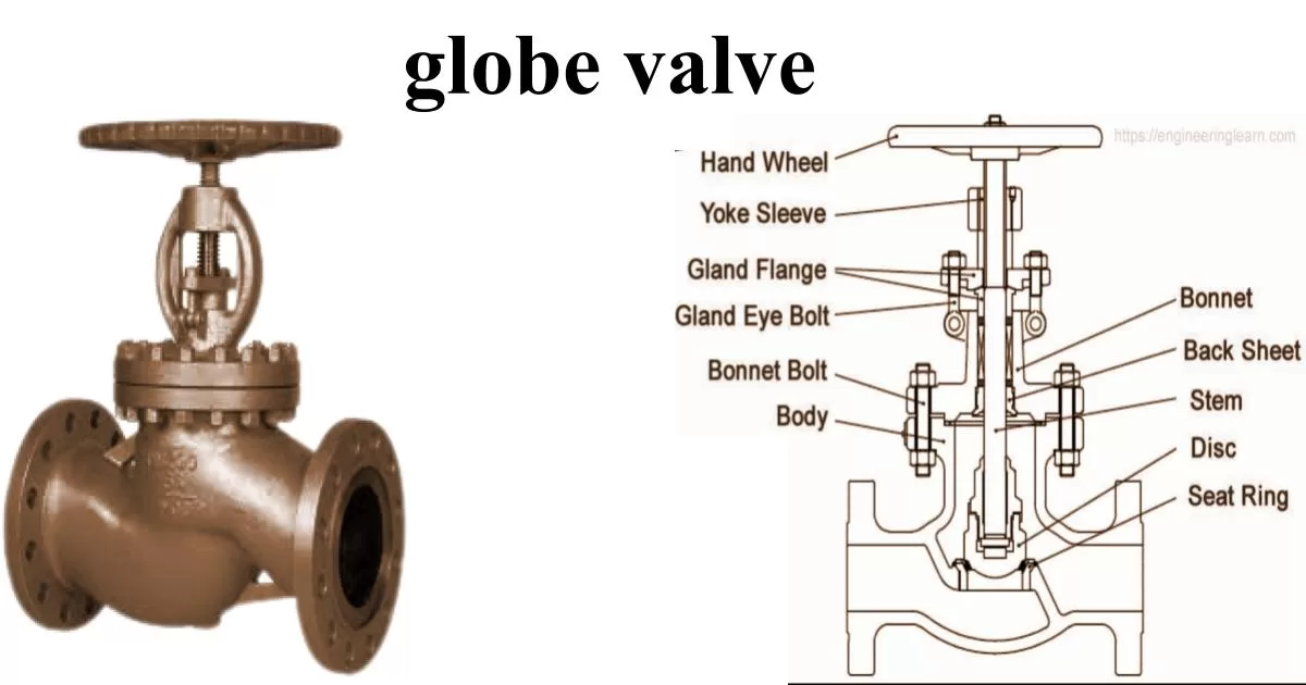
Body: The body of the Globe valve is typically made of cast iron, bronze, or stainless steel and is designed to withstand high pressure and temperature.
Bonnet: The bonnet of the Globe valve covers the stem and is connected to the body of the valve by bolts. The bonnet also contains the packing and stem seal.
Stem: The stem of the Globe valve is responsible for opening and closing the valve. It is typically made of stainless steel and connects to the handwheel or actuator.
Disc: The disc of the Globe valve is responsible for controlling the flow of fluid or gas through the valve. It is typically made of stainless steel or other corrosion-resistant alloys.
Seat: The seat of the Globe valve provides a tight seal against the disc to prevent leakage. It is typically made of materials such as bronze or stainless steel.
Packing: The packing of the Globe valve provides a seal around the stem to prevent leakage. It is typically made of materials such as graphite or PTFE.
Prevent Leaks with Our Comprehensive Leakage Class for All Types of Valves
The leakage classes for different types of valves are as follows:
- Globe Valves: Globe valves typically have a leakage class of Class III or IV. Class III leakage allows for a maximum of 0.1% of rated valve capacity per year, while Class IV leakage allows for a maximum of 0.01% of rated valve capacity per year.
- Ball Valves: Ball valves typically have a leakage class of Class V or VI. Class V leakage allows for a maximum of 0.01% of rated valve capacity per year, while Class VI leakage allows for a maximum of 0.00001% of rated valve capacity per year.
- Butterfly Valves: Butterfly valves typically have a leakage class of Class VI, which allows for a maximum of 0.00001% of rated valve capacity per year.
- Check Valves: Check valves typically have a leakage class of Class VI, which allows for a maximum of 0.00001% of rated valve capacity per year.
It is important to note that the selection of the appropriate leakage class for a valve is dependent on the specific application requirements, such as the type of fluid or gas being conveyed, the temperature and pressure ranges, and the required flow rate. Consultation with valve experts or suppliers can help ensure that the appropriate leakage class is selected for the specific application.
Maximizing Efficiency: How to Calculate Pressure Drop in globe Valves for Optimal Performance
The pressure drop across a Globe valve can be calculated using the following formula:
ΔP = K * ρ * Q^2
Where: ΔP = pressure drop (in pounds per square inch or PSI) K = pressure drop coefficient (dimensionless) ρ = fluid density (in pounds per cubic inch or lb/in^3) Q = flow rate (in cubic inches per second or in^3/s)
The pressure drop coefficient, K, is a measure of the valve’s resistance to flow and can be obtained from valve manufacturers or from industry standards such as the Crane Technical Paper 410. The flow rate, Q, can be determined based on the required flow rate for the specific application.
To calculate the pressure drop across a Globe valve, the fluid density and flow rate must be known. These values can be determined based on the fluid properties and the required flow rate for the specific application.
It is important to note that the pressure drop across a Globe valve should be within an acceptable range for the specific application to ensure proper system performance. Consultation with valve experts or suppliers can help ensure that the pressure drop across the selected Globe valve meets the necessary application requirements.
Gate Valve vs Globe Valve: Which is the Better Choice for Your Application?
Globe valves and gate valves are two commonly used types of valves in industrial applications. While both Globe valves and Gate valves are designed to regulate flow, they differ in their design and performance characteristics.
- Design: Globe valves have a spherical body with a baffle and a disc that moves perpendicular to the flow axis to control the flow. They are designed for throttling and regulating flow in applications that require precise control. Gate valves, on the other hand, have a flat or wedge-shaped gate that moves up and down to control the flow. They are designed for on-off applications where full flow or no flow is required.
- Performance Characteristics: Globe valves have a higher pressure drop compared to gate valves. This means that they can be less efficient in applications where minimizing pressure drop is critical. However, Globe valves are better suited for applications that require precise control of flow rate, as they can provide finer adjustments to flow. Globe valves are also less prone to vibration and cavitation compared to gate valves.
- Gate valves, on the other hand, have a lower pressure drop and can handle higher flow rates compared to Globe valves. They are better suited for applications where low resistance to flow is critical. Gate valves are also more prone to vibration and cavitation compared to Globe valves, making them less suitable for applications where precise control is necessary.
In terms of maintenance, Globe valves are typically easier to maintain compared to Gate valves, as they have fewer moving parts and are less prone to wear and tear.
Globe Valve vs Piston Valve: Which is the Right Choice for Your Flow Control Needs?
- Design: Globe valves have a spherical body with a baffle and a disc that moves perpendicular to the flow axis to control the flow. They are designed for throttling and regulating flow in applications that require precise control. Piston valves, on the other hand, have a piston that moves back and forth within a cylinder to control the flow. They are designed for high-pressure applications where tight shutoff is required.
- Performance Characteristics: Globe valves have a higher pressure drop compared to piston valves, which means they can be less efficient in applications where minimizing pressure drop is critical. However, Globe valves are better suited for applications that require precise control of flow rate, as they can provide finer adjustments to flow. Globe valves are also less prone to vibration and cavitation compared to piston valves.
- Piston valves, on the other hand, can handle higher pressures compared to Globe valves, making them better suited for high-pressure applications. Piston valves are also better suited for applications that require tight shutoff, as they can provide better sealing than Globe valves. However, piston valves may not be suitable for applications that require precise control of flow rate, as they may not provide the same level of control as Globe valves.
In terms of maintenance, Globe valves are typically easier to maintain compared to piston valves, as they have fewer moving parts and are less prone to wear and tear.
Globe Valve vs Butterfly Valve vs Ball Valve: Understanding the Differences and Choosing the Right Option for Your Application
- Design: Globe valves have a spherical body with a baffle and a disc that moves perpendicular to the flow axis to control the flow. They are designed for throttling and regulating flow in applications that require precise control. Butterfly valves, on the other hand, have a disc that rotates around a central axis to control the flow. They are designed for on-off applications and can handle high flow rates. Ball valves have a spherical ball with a hole through the center that rotates to control the flow. They are also designed for on-off applications and can handle high flow rates.
- Performance Characteristics: Globe valves have a higher pressure drop compared to butterfly valves and ball valves. This means that they can be less efficient in applications where minimizing pressure drop is critical. However, Globe valves are better suited for applications that require precise control of flow rate, as they can provide finer adjustments to flow. Globe valves are also less prone to vibration and cavitation compared to butterfly valves and ball valves.
- Butterfly valves and ball valves both have lower pressure drops compared to Globe valves, which means they can be more efficient in applications where minimizing pressure drop is critical. They are both better suited for on-off applications where full flow or no flow is required. However, butterfly valves and ball valves may not be suitable for applications that require precise control of flow rate, as they may not provide the same level of control as Globe valves.
In terms of maintenance, butterfly valves and ball valves are typically easier to maintain compared to Globe valves, as they have fewer moving parts and are less prone to wear and tear.
Ensuring Proper Installation: A Comprehensive Checklist for globe Valve Installation
- Verify that the valve is the correct size and type for the application.
- Inspect the valve body for defects, such as cracks or corrosion, before installation.
- Ensure that the valve is properly aligned with the piping system and that the flanges match.
- Use the correct gasket and torque values for the flange bolts to prevent leakage.
- Apply the correct type and amount of lubrication to the stem and packing.
- Properly position the actuator and ensure that it is securely attached to the valve.
- Confirm that the actuator is the correct size and type for the valve and the application.
- Verify that the electrical and pneumatic connections are properly installed and secure.
- Conduct a leak test on the valve and the piping system before placing the valve into service.
- Perform a functional test of the valve to ensure proper operation and safety.
- Install appropriate safety measures, such as pressure relief valves, if necessary.
- Keep the valve and its surroundings clean and free from debris during installation.
Ensure Optimal Performance: A Comprehensive Globe Valve Inspection Checklist
- Check for signs of damage or wear and tear, such as cracks or corrosion, on the valve body, stem, and other parts.
- Verify that the valve is operating smoothly and that there are no leaks around the valve body or stem.
- Confirm that the valve is properly aligned with the piping system and that the flanges match.
- Check the valve packing for wear and proper lubrication. Adjust or replace the packing as needed.
- Verify that the actuator is operating smoothly and that there are no leaks or damage to the electrical or pneumatic connections.
- Check the position of the valve and actuator to ensure proper alignment.
- Inspect any safety devices, such as pressure relief valves, for proper operation.
- Clean and remove any debris or buildup around the valve and surrounding areas.
- Conduct any necessary repairs or replacements, such as replacing worn gaskets or fixing leaks.
- Keep records of the inspection and any maintenance performed.
Troubleshooting globe Valve Failures: Identifying Causes and Solutions for Optimal Performance
Valve Leakage:
Leakage can be caused by worn or damaged valve seats, improper installation or maintenance, or excessive pressure. Troubleshooting steps include:
- Inspect the valve seat and replace if worn or damaged.
- Verify proper installation and torquing of the flange bolts
- Reduce pressure if it exceeds the valve’s rated capacity
Valve Sticking:
Sticking can be caused by corrosion, sediment buildup, or inadequate lubrication. Troubleshooting steps include:
- Inspect the valve body and stem for corrosion and clean or replace as necessary
- Remove sediment buildup around the valve and clean or replace as necessary
- Apply the appropriate lubrication to the stem and packing
Valve Noise:
Noise can be caused by excessive fluid velocity or improper valve sizing. Troubleshooting steps include:
- Verify that the valve is properly sized for the flow rate
- Reduce fluid velocity by installing a flow restrictors or throttling device
Valve Actuator Failure:
Actuator failure can be caused by electrical or pneumatic issues, worn gears, or mechanical failure. Troubleshooting steps include:
- Check electrical or pneumatic connections and repair or replace as necessary
- Inspect gears and replace if worn
- Check for any mechanical failure and repair or replace as necessary
Valve Seizure:
Seizure can be caused by corrosion, sediment buildup, or inadequate lubrication. Troubleshooting steps include:
- Inspect the valve body and stem for corrosion and clean or replace as necessary
- Remove sediment buildup around the valve and clean or replace as necessary
- Apply the appropriate lubrication to the stem and packing
Selecting the Right Material: A Comprehensive Guide to Globe Valve Material Specifications and Grades
Globe valves can be constructed from a variety of materials, depending on the specific application and the fluid being controlled. Below are some commonly used materials and their specifications:
- Valve Body and Bonnet Materials:
- Carbon Steel (ASTM A216 WCB)
- Stainless Steel (ASTM A351 CF8, CF8M, CF3, CF3M)
- Cast Iron (ASTM A126)
- Ductile Iron (ASTM A536)
- Valve Trim Materials:
- Stainless Steel (ASTM A276, A182)
- Bronze (ASTM B62, B148)
- Monel (ASTM B164)
- Hastelloy (ASTM B574)
- Packing Materials:
- Graphite
- PTFE
- Braided Graphite
- Gasket Materials:
- Graphite
- Spiral Wound
- Ring Joint
It is important to note that material specifications can vary depending on the specific manufacturer and application. It is recommended to consult with valve suppliers or industry experts to ensure the appropriate material selection for a Globe valve application. Additionally, it is important to ensure that any materials used are compatible with the fluid being controlled and any other components in the piping system to prevent corrosion or damage.

